Singlemode fiber connections provide analog transmission success
A pair of properly considered factors will ensure the effective use of singlemode fiber with analog transmission systems.
Irwin Math, Math Associates, a division of Communications Specialties Inc.
The use of multimode fiber with both analog and digital fiber-optic transmission systems is quite well established and, with the exception of making certain the connectors are installed properly and the fiber ends are clean, usually poses no operational problem. This is not necessarily the case when using singlemode fiber. In this situation there are both fiber- and fiber-connector-related factors that can easily cause perfectly good electronics to operate poorly or, in some cases, not at all. With a good understanding of a few basic facts, however, the system installer or specifier can take steps to assure that everything performs as expected.
Choosing a connector
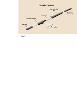
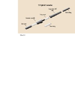
The most common optical connector in use today with multimode fiber is the ST type (see Fig. 1). This connector is spring-loaded and installs very much like a miniature bnc-type RF connector. A quick twist of the fingers and it is mated. It is so popular and easy to connect that higher-tolerance versions have been developed for use with singlemode fiber to offer the same versatility. However, the very feature responsible for the ST`s popularity also causes problems when the singlemode version of the connector is employed with an analog system.
Because the center pin of an ST connector is spring-loaded, any strain, vibration, or pulling on the fiber-optic cable attached to the connector can cause the center pin to move slightly. The core of singlemode fiber is only 8 to 10 microns in diameter (0.0003 to 0.0004 in) so that any amount of movement on that order results in increased attenuation at the optical junction. Since many analog fiber-optic systems employ intensity modulation of the light-emitting diode or laser diode used as the light source, this varying attenuation shows up as an unwanted modulation product. In an audio system, the result is fading or fluttering of the signal at the fiber-optic cable vibration rate. In a video transmission system, the picture can visibly dim or flicker at the vibration rate and even occasionally lose sync lock.
Digital systems are not quite as prone to varying attenuation, since they usually have a minimum threshold level above which the system triggers properly. When operated at or near their specified optical attenuation limit, however, a digital system can still exhibit erratic behavior in the form of compromised bit-error rates or even complete signal dropout if the optical input varies too much.
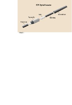
The solution is to be certain that the fiber-optic cable is absolutely mechanically secure and to employ a singlemode optical connector that is not spring-loaded and that can be physically locked in place. A connector of this type is the fcpc (see Fig. 2). This connector has a precision tip that is not spring-loaded. It also has a locating tab that is very much like the ST, but features a screw-down ferrule that does not allow the tip to move when the attached cable is flexed. This stability comes from the various internal strength members and jacket that are crimped directly to the ferrule while the fiber and buffer tube portions are crimped to the center pin. When the connector is mated and "screwed down," nothing moves.
Other than this rigid mechanical arrangement, the polishing techniques and fixtures for the fcpc are virtually the same as for the ST connector. Since fcpc connectors are readily available and not really any more difficult to install than STs, their use should be standard for analog intensity-modulation applications.
Reducing back reflection
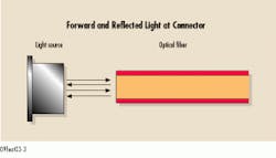
A second problem that often occurs with singlemode analog transmission systems arises from backreflection, otherwise known as return loss. Whenever light passes from one medium to another, a certain amount of light is reflected back to the source of the light (see Fig. 3). In the case of fiber-optic cable where the interface is fiber/ air, the amount of backreflection (the fiber return loss) is on the order of 4%. This return loss is negligible in a multimode system when the optical emitter is a light-emitting diode, but it can cause problems in a singlemode system when the emitter is a laser diode.
When light at the same wavelength as that produced by the laser diode re-enters the laser cavity due to backreflection, it mixes with the photons being amplified within the cavity. Depending on its phase, this back-reflected light either adds to or subtracts from the laser output. Since the phase of the reflected light is also a function of the length of the fiber-optic cable, any mechanical variation in cable length will have an effect on it. The result is that the phase of the reflected light is generally unstable and, when it combines with the light in the laser cavity, the amplitude of the laser output also becomes unstable. As already mentioned, any uncontrolled variation in light output in anintensity-modulated system shows up as an unwanted modulation product, and the demodulated electrical output signal becomes distorted.
The solution, obviously, is to try to reduce backreflection to as low a level as possible. This can be accomplished by various methods of finishing the end of the fiber in the optical connector.
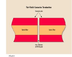
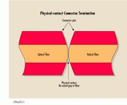
The air-gap in the interface of a typical flat-finished connector (see Fig. 4) results in a 4% amount of backreflection (roughly 15 dB). This amount is enough to cause a video picture to exhibit wavy "artifacts" that can make viewing annoying or produce a whine or audible whistle in the background of an audio system. There are two ways to minimize these reflections. In the so-called physical contact (or PC) finish (see Fig. 5), the fiber is rounded and actually touching its mate, so there is minimal air-gap between the faces of the two fibers and the true surface available for reflections is small. The PC finish adds at least 15 to 25 dB of additional backreflection reduction and can minimize unwanted signals to the point where they are not objectionable.
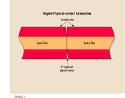
The ultimate in finishing, however, is the angled PC connector (see Fig. 6). In this finish, backreflection is first reduced by the physical contact of the mated connectors--and then virtually eliminated by the fact that the fiber ends are not parallel but are ground at a small angle of about 8°. This angle refracts and reflects any light from the fiber end that normally would be reflected out of the fiber. Angled finishes can easily result in a 60- to 70-dB reduction of backreflection and produce perfect, artifact-free signals. The only concern regarding the angled PC interface is that in a butt splice, both connectors must be angled and properly aligned or attenuation will be severe. The same type of tools and fixtures that are used for flat finishes are available for angled finishes.
In cases where a system is installed already and backreflection problems are present, a solution that sometimes "saves the day" is the application of a tiny amount of an optical coupling gel at the fiber ends in the connector. This gel is a silicone compound whose index matches the two glass surfaces, thereby minimizing reflections. This gel will not evaporate, so it can be left in place indefinitely--but it does have a tendency to pick up dust and dirt when the connectors are apart. If adequate care is taken, however, the use of optical coupling gel often can make a poorly performing system operate properly.
With all that in mind, there is no reason why an amplitude-modulated analog transmission system cannot be operated with singlemode fiber and produce signals that are as clean and noise-free as with any other method. In addition, the cost savings of such a system is easily worth the slight degree of extra care required in setting it up properly. u
Irwin Math is director of fiber-optic engineering at Math Associates (Hauppauge, NY), a division of Communications Specialties Inc.Fig. 6. An angled physical-contact connection provides the maximum amount of backreflection reduction. It is recommended for use with high-performance analog transmission systems.
