Cost-effective dispersion management for emerging network upgrade paths
Matching the right fiber with the right dispersion-compensation module -- and perhaps changing amplification techniques -- will provide the surest foundation for network capacity growth at the lowest possible network cost.
Lars Grüner-Nielsen, C. Christian Larsen, Max Nelson, and Pat Emery
OFS
Compensation techniques
Historically, dispersion management was approached in two ways, first by changing the dispersion characteristics of the transmission fiber and later by developing dispersion-compensating fiber (DCF) to cancel the dispersion built up as signals traveled through the network. Alternative dispersion-compensation techniques have been demonstrated, but have so far only found use in limited applications such as tunable per-channel post compensators.
In the area of new transmission fibers, dispersion-shifted fiber (DSF -- ITU G.653) was introduced for single-channel high-speed systems; later, non-zero dispersion-shifted fiber (NZDF -- ITU G.655) was developed for WDM systems. NZDF improved many aspects of system performance compared to conventional single-mode fiber by reducing dispersion in the wavelength spectrum around 1550 nm that is used by erbium-doped fiber amplifiers (EDFAs). However, some dispersion needed to be retained to suppress non-linear effects between the WDM channels.
DCF also has undergone an evolution. The first DCF merely had to compensate for the cumulative bulk amount of dispersion because only a few WDM channels were used over a narrow window in the fiber's optical spectrum. However, as transmission system technology developed to use wider bands of the optical spectrum, DCF has had to evolve to compensate not only for bulk dispersion but also to compensate for the fiber's dispersion variation with wavelength (dispersion slope) and, most recently, to accommodate slope mismatches between the DCF and transmission fiber (dispersion curvature).
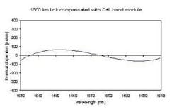
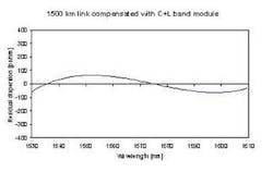
Dispersion-slope compensation is realized by matching the relative dispersion slope (RDS) of the DCF to that of the transmission fiber,2 where RDS is the ratio of dispersion slope to dispersion. RDS at the 1550-nm wavelength for a range of common C-band transmission fibers varies from 0.0035 to 0.02 nm-1. DCF with matching RDS has been demonstrated for most common commercial transmission fibers.3,4,5,6,7,8,9,10,11To compensate longer-reach and higher-speed networks, one must also cope with the curvature differences between the dispersion in the DCF versus the transmission fiber. For most transmission fibers, the curvature of the dispersion over a broad wavelength range is quite low, but that does not always hold for all DCFs. With proper design, the dispersion curvature of the DCF can be minimized.3,7,10,11 However, even where DCFs have been optimized for transmission fibers, the usable bandwidth due to dispersion curvature depends on the RDS of the transmission fiber.12 Thus, a low RDS in conjunction with a dispersion curvature matched to the transmission fiber will yield the largest dispersion compensated bandwidth. Figure 1 shows the link dispersion for 1,500-km links using such an approach.Dispersion compensation and amplification
However, EDFA technologies cannot take full advantage of the cost-savings enabled by this dispersion-compensating technology. EDFA-based amplification technologies require splitting the spectrum into bands. Consequently, the broadband advantages of today's cutting-edge dispersion-compensation technologies cannot be realized, as costs are greatly increased by the need for separate DCF for each band through channel splitting, and because channels are lost between the bands.
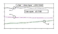
A solution to the problem of channel splitting in EDFA amplification is to switch to an all-Raman amplification system. In such a system, there is no need for band splitting -- the entire bandwidth can be used. An additional benefit is that one Raman-pumped DCF can replace two passive DCFs, four EDFAs and two WDMs, leading to a much more cost-efficient system. Such all-Raman systems have already been tested, demonstrating record capacities and distances.4,13Raman amplification further has the attractiveness of providing gain at any wavelength, limited only by the pump wavelengths available. Broad gain spectrum extending beyond the EDFA band can be achieved by using several pump wavelengths.14,15Figure 2 illustrates an example of Raman gain performance for a DCF module. To achieve amplification in both C- and L-bands, the module was pumped at five wavelengths in the range from 1427 nm to 1502 nm, with a total pump power of 1 W. A gain of 10 dB is achieved, and due to the optimized choice of pump wavelengths, the gain ripple is very low -- less than ±0.17 dB.Summary
It is clear that bandwidth demand continues to grow at a very brisk pace. As a result, network planners will have to continuously deploy ever-more bandwidth at ever-greater cost-efficiency. What is not clear is which migration growth path will prove to be the most cost-efficient at the various times in the future when new capacity needs to be deployed.
Regardless of whether greater speed, tighter channel spacing, wider bandwidths, or greater distances prove most cost-efficient, every path requires chromatic-dispersion technologies that compensate for dispersion, dispersion slope, RDS, and dispersion curvature while minimizing total system polarization mode dispersion (PMD). It is also likely that band-splitting losses and costs combined with the advantages of discrete Raman amplification gain will make Raman amplification regimes a likely candidate for future network deployment. Regardless of which technologies win out, network planners can ensure their fiber networks will be optimized for any migration path by selecting an appropriate combination of transmission fiber and DCM.
References:
1) L. Nelson, "Challenges of 40 Gb/s WDM Transmission," OFC'01, paper ThF1.
2) L. Grüner-Nielsen, S.N. Knudsen, B. Edvold, T. Veng, D. Magnussen, C.C. Larsen, and H. Damsgaard, "Dispersion Compensating Fibres," Optical Fibre Technology, Vol. 6 (2000), pp. 164-180.
3) L. Grüner-Nielsen, Y. Qian, B. Pálsdóttir, Y.Qian, P.B. Gaarde, S. Drybøl, T. Veng, R. Boncek, and R. Ling, "Module for Simultaneous C+L-band Dispersion Compensation and Raman Amplification," OFC '02, paper TuJ6.
4) B. Zhu, L. Leng, L. E. Nelson, L.Gruner-Nielsen, Y. Qian, J. Bromage, S. Stulz, S. Kado, Y. Emori, S. Namiki, P. Gaarde, A. Judy, B. Palsdottir, and R. Lingle, "3.2-Tb/s (80 x 42.7 Gb/s) Transmission over 20 x 100km of Non-zero Dispersion Fibre with Simultaneous C+L-band Dispersion Compensation," OFC'02, paper FC8.
5) J. Bromage, L. E. Nelson, P. J. Winzer, and C. J. McKinstrie "Raman-enhanced Pump-signal Four-wave Mixing in Bidirectionally-pumped Raman Amplifiers," OAA'02, paper OWA5.
6) L. Grüner-Nielsen, S.N. Knudsen, B. Edvold, T. Veng, D. Magnussen, C.C. Larsen, and H. Damsgaard, "Dispersion Compensating Fibres," Optical Fibre Technology, Vol. 6 (2000), pp. 164-180.
7) M. Wandel, P. Kristensen, T. Veng, Y. Qian, Q. Le, and L. Grüner-Nielsen, "Dispersion Compensating Fibres for Non-zero Dispersion Fibres," OFC'02, paper WU1.
8) M.J. Li, "Recent Progress in Fibre Dispersion Compensators," ECOC'01, paper Th.M.1.1.
9) T. Kato, H. Hirano, K. Fukuda, A. Tada, M. Onishi, and M. Nishimura, "Design Optimisation of Dispersion Compensating Fibre for NZ-DSF Considering Nonlinearity and Packaging Performance," OFC'01, paper TuS6.
10) L. Grüner-Nielsen and B. Edvold, "Status and Future Promises for Dispersion Compensating Fibres," ECOC'02, paper 6.1.1.
11) Y. Qian, S. Dyrbøl, J.S. Andersen, P.B. Gaarde, C.G. Jørgensen, B. Pálsdóttir, and L. Grüner-Nielsen, "Bi-directionally Pumped Discrete Raman Amplifier with Optimised Dispersion Compensation for Non-shifted Transmission Fibre," ECOC'02, paper 4.1.6.
12) J. Rathje and L. Grüner-Nielsen, "Relationship between Relative Dispersion Slope of a Transmission Fibre and the Usable Bandwidth after Dispersion Compensating," ECOC'02, paper P1.23.
13) A. H. Gnauck, G. Raybon, S. Chandrasekhar, J. Leuthold, et al., "2.5 Tb/s (64x42.7 Gb/s) Transmission over 40x100 km NZDSF Using RZ-DPSK Format and All-Raman-Amplified Spans," OFC'02, paper FC2.
14) K. Rottwitt and H.D. Kidorf, "A 92 nm Band Width Raman Amplifier," OFC'98, PD6.
15) Y. Emori, "Ultrabroadband Fiber Raman Amplifiers," ECOC'02, paper S3.02.
Lars Grüner-Nielsen, Ph.D., is project manager, fiber development, Specialty Photonics Division; C. Christian Larsen, Ph.D., is vice president, Specialty Photonics Division; Max Nelson is senior manager of strategic business planning; and Gary P. (Pat) Emery is director of strategic planning at OFS (Norcross, GA).


