Modern day high-bandwidth conventional oscilloscopes are typically supplied with a maximum of four input channels (and with as few as one or two channels at a higher bandwidth rating), owing to practical design tradeoffs between bandwidth and channels. However, dual-polarization quadrature phase-shift keyed (DP-QPSK) or quadrature amplitude-modulated (16-QAM) coherent optical modulation systems analysis requires real-time analog-to-digital conversion of four electrical tributaries using very high real-time analog bandwidths of 30 GHz to 45 GHz. Other types of encoding may require many more channels at half of this bandwidth.
To meet these needs, oscilloscope manufacturers have developed methods to connect multiple conventional oscilloscopes, each with their own acquisition timebase, using 10-MHz external clocking. However, this leads to system inaccuracies and requires significant operator time to connect the oscilloscopes. A modular oscilloscope system could provide much higher synchronization accuracy by using a single timebase for all acquisition modules and a single integrated trigger circuit to operate the entire system.
Conventional oscilloscope architecture
The basic architecture for a single channel in a digital storage oscilloscope includes a 10-GHz clocked timebase that drives a sampler and an analog-to-digital converter (ADC), as well as an integrated trigger circuit. Input signals are digitized and stored into memory, and the trigger circuit instructs the memory chip when to cease updating and to transfer stored data for processing and display.
The timebase portion consists of an oscillator operating at 10 MHz. The output of this oscillator passes through a phase-locked-loop (PLL) frequency multiplier to achieve the required 10 GHz to drive the sampler and trigger circuit. The clock module also accepts an external 10 MHz reference source and can output its own 10-MHz reference clock for use with an external device (which could be another oscilloscope). The timebase is the “heartbeat” of the acquisition system, and any variation in the phase of a clock cycle relative to an ideal clock is defined as the time interval error (TIE, or phase jitter).
Connecting two (or more) conventional oscilloscopes: timebase phase and trigger jitter errors
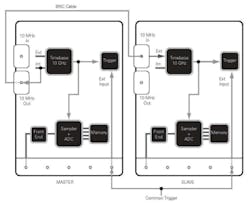
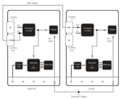
Connecting multiple conventional oscilloscopes requires synchronizing the phase of each timebase using the 10-MHz reference clock output from one oscilloscope to the reference clock input of another. This is shown in Figure 1 for two conventional oscilloscopes.
Figure 1. Synchronizing two conventional oscilloscopes
This method is not perfect, and leads to an increase in the total TIE of the system timebase. A 10-MHz timebase clock signal also has a relatively slow slew rate, and such low slew rates are susceptible to small amplitude noise effects that manifest as time uncertainty, which increases the TIE further. In addition, the use of a PLL to multiply the frequency of the 10-MHz clock by 1000 times to 10 GHz can add a non-trivial amount of TIE. Lastly, since the 10 MHz reference must pass through a cable to reach other oscilloscopes, noise may infiltrate the timebase clock signal, causing its TIE to potentially increase. The total TIE from all of these sources results in inaccurate sample point placement, and phase errors in the measurement.
The trigger systems in each conventional oscilloscope must also be integrated so that when a valid trigger condition is found, both oscilloscopes are able to trigger simultaneously. Typically, BNC cables connect auxiliary inputs/outputs of the conventional oscilloscopes to permit cross-triggering. These auxiliary inputs/outputs are typically low in bandwidth, which reduces the slew rate of the trigger signal and leads to an increase in the amount of time uncertainty in triggering. Furthermore, by integrating the triggers of two conventional oscilloscopes, the total trigger increases as the quadrature sum of each individual oscilloscope’s trigger jitter.
Consider the impact of all of the combined TIE (phase) and trigger jitter errors with 28-Gbps signals on two conventional oscilloscopes connected using a 10-MHz reference clock. These TIE and trigger jitter errors cause dynamic skew between the signals, or skew that cannot be eliminated with calibration processes. At 28 Gbps, the unit interval (UI) is approximately 36 ps. If the conventional oscilloscopes are connected together to yield 1 psrms of total timebase phase error and trigger jitter (or 6 pspk-pk for three standard deviations) between acquisition systems, as is typically specified, the result becomes an added phase uncertainty of nearly 20% of the unit interval due solely to the oscilloscope acquisition system. This is more than enough to wreak havoc on the phase relationship of the captured signal, and is especially noteworthy when working with phase and frequency modulated signals, such as DP-QPSK or 16-QAM signals.
Modular oscilloscope synchronization advantages
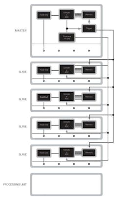
All of the dynamic skew issues discussed with connecting multiple conventional oscilloscopes can be resolved by designing the acquisition system of the oscilloscope to be modular (see Figure 2). In the modular oscilloscope design, a single distributed 10-GHz clock (1000 times faster than a 10-MHz reference clock) is generated in a master acquisition module and then distributed to multiple slave acquisition modules. Since the modular oscilloscope uses a distributed 10-GHz timebase tied directly to all of the samplers and ADCs of each slave, there are not multiple timebases to synchronize. Furthermore, with a 10-GHz clock rate, the slew rate of this clock is very high and results in no measurable increase in the TIE as a result of amplitude noise. Finally, since the slaves do not generate their own timebases, there are no additional PLLs in-circuit that would add to the acquisition system TIE.
Figure 2. Modular oscilloscope designs significantly simplifies synchronization
Also eliminated with a modular oscilloscope system are the major problems associated with integrating the triggers of multiple conventional oscilloscopes. The master acquisition module performs all triggering for the entire system using a single integrated trigger circuit made possible with PCI Express synchronizing cable connects between the master and each slave. With this approach, the master directly controls the sampler, ADCs, and memory of each channel in the slaves. Thus, there is nothing to synchronize vis-à-vis the trigger. Moreover, since only a single trigger circuit exists, the trigger jitter of the system is only that arising from the single trigger circuit. If the acquisition is a single-shot acquisition then there is no trigger jitter present at all, since there is only a single trigger for all oscilloscope acquisition modules.
Lastly, the modular design has the advantage of not requiring complicated and inaccurate connection schemes, and all oscilloscope captures are conveniently displayed on a single display in the master. A central processing unit with a server-class multi-core CPU operating at an effective clock rate of 33.6 GHz and accommodating up to 192 GB of RAM is also included.
The complete modular oscilloscope synchronization approach results in many oscilloscope channels at very high bandwidths—as many as 5 channels at 45 GHz, 10 channels at 30 or 36 GHz, or 20 channels at 20 GHz—with one-fourth the jitter between all channels compared to connecting conventional oscilloscopes. In addition, there is no hassle associated with connecting and debugging the complete system. This approach is ideal for optical coherent modulation analysis of DP-QPSK, 16-QAM, optical orthogonal frequency-division multiplexed (OFDM) signals, or even multiple-input/multiple-output (MIMO) formats.
Kenneth Johnson is senior product marketing manager at LeCroy Corp.


