Bend matters, Part 1: A look at macrobending
Wherever optical fiber is deployed, from transoceanic links to the final drop to the residential unit, protecting the optical power budget is of paramount importance.
Loss matters. This fundamental truth is easily understood when long-haul links are being deployed that must cope with state-of-the-art 100-Gbps transmission. Optical signal-to-noise ratio (OSNR) improvement of 10 dB per span is required to upgrade from 10 Gbps to 100 Gbps. While advanced modulation formats and forward error correction (FEC) can provide some of the improvement, low-attenuation fiber is necessary to enable this upgrade at the lowest cost by minimizing the need for additional amplifiers and signal regeneration.
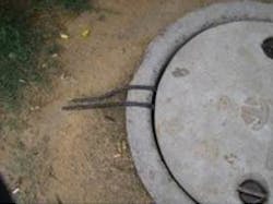
In addition, low attenuation is especially important in developing countries where shallow, direct-buried installation of cables is common (Figure 1). Such cables often require repair due to damage from mechanical excavation. Each restoration of a cable cut (by fusion splicing the broken fiber ends) can increase the signal loss by up to 0.2 dB, as the repair is often performed quickly in potentially unfavorable environmental conditions due to the need for rapid service restoration. A few cuts can rapidly exceed a power budget designed with too little margin.
than being installed into a duct, cable emerges
from the access point to be directly buried in
a shallow trench.
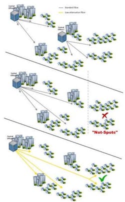
Equally, loss matters in access networks. First, an operator can realize considerable savings if each central office can cover a wider range of customers. A low-attenuation singlemode fiber may increase the coverage area by up to 19% by reducing the number of central offices necessary to support a city and its suburbs. Significant operational savings can derive from the closure of redundant buildings (Figure 2).
Central Office 2 cannot be reached from Central Office 1
in the event of closure of the former. Subsequent creation
of “not-spots” (areas without service) hinders central
office closure. With increased reach of low attenuation
fiber, suburbs can be reached from Central Office 1,
rendering Central Office 2 potentially redundant.
Second, between the exchange and termination point, the fiber may experience bending events that increase fiber loss by more than the intrinsic attenuation of the fiber. Such losses increase installation time and expense as power-drop issues are identified and corrected. Bending losses come from two sources. This article reviews macrobending; a companion article examines microbending. Fortunately, both phenomena can be mitigated by exploiting recent advances in glass and coating technology.
Macrobending basics
Macrobending is the attenuation associated with bending or wrapping the fiber. Light can “leak out” of a fiber when it is bent. As the bend becomes tighter, more light escapes. (Figure 3).
from a straight deployment, some light is refracted from the fiber. As
the bend tightens, more light is lost.
Macrobending loss, measured in decibels, increases at longer wavelengths where the optical confinement of the light is weaker. It also increases linearly with the number of turns.
Traditionally, macrobending was not a limiting effect when cables were mostly of loose-tube or ribbon design and installed into ducts. The tightest bends incurred by fibers were in splice trays, where excess fiber would be stored in loops after jointing. This was reflected in the macrobending specification of ITU-T Recommendation G.652, where a minimum bend radius of 30 mm was defined to reflect typical splice tray dimensions and 100 turns were agreed upon to simulate the total excess fiber from all the splice sites between repeaters.
But macrobending effects become more pronounced in networks installed close-to and within the building. Prevalent in this segment of the network are low-diameter mini-cables that are stripped-back designs, compared to the traditional sheathed loose-tube and ribbon cables. Lightweight and highly flexible, these new designs are preferred for their space efficiency (when installed into commensurately small micro-ducts) and ease of handling and routing (when installed on the inside and outside of buildings along tortuous paths). Bend radii of much less than 30 mm therefore have become commonplace (Figure 4), exceeding the capability of legacy singlemode fiber and the specifications within G.652.
conditions that fibers are subject to in-building.
For example, the power budget for GPON is commonly set at 28 dB. Once losses for fiber attenuation, splitting, connectorization, and splices are considered, only ~1 dB may be allowed for loss-inducing bends entering or inside the building. Bends can be as severe as ~5 mm radius, and the macrobending loss induced by just one quarter turn of conventional singlemode fiber would exceed this allowance.
Overcoming macrobending issues
Fiber manufacturers have responded to the challenge with a range of “enhanced bending” products. To address the shift towards “bend insensitive” fiber, ITU-T Recommendation G.657 was developed to categorize the different levels of performance that are available (see Table below).
improved bending fibers defined in ITU-T Recommendation G.657.
Category A fibers are required to also comply with the established ITU-T Recommendation G.652 to provide backwards compatibility with the existing installed base. With this constraint lifted, Category B fibers may achieve additional bend resistance by exceeding limits defined in Rec. G.652. In fact, the discerning buyer need not compromise between performance and backward compatibility. The very best bend resistant fibers exceed the 5-mm radius requirements of Rec. G.657 category B3 while retaining full compliance to Rec. G.652.
These three categories of performance enable the network owner to intelligently select products that are appropriate to the degree of bending that may be incurred. Failure to specify to an adequate category may lead to higher costs at installation, as rogue bends cause the power budget to be exceeded and installation teams incur time and money to locate and correct these events. Inadequate provisioning also exposes the operator to higher churn (loss of subscribers to competition) if the network is perceived to be unreliable due to outages when tight bends get inserted or occur intermittently over the life of the installation. Given that the final drop to the termination point is inside the subscriber’s home, tight bends may easily be created inadvertently during redecoration, home improvement, and sundry other mundane events of domestic life.
Between the exchange and the building, where the mini-cable is reasonably well protected, Rec. G.657.A1 fiber is often sufficient to cope with the path of the small-bore mini-duct. Within the building however, to allow rapid installation and to ensure resilience to damage due to normal domestic activity, Rec G.657.B3 fiber should be chosen to avoid the cost of correcting installations incurred by operators who have elected to deploy insufficiently bend-resistant fiber.
In the face of the two important bending loss mechanisms (microbending, which is discussed in our companion article, and macrobending) the best optical performance is ensured by the combination of best glass and best coating. Fibers designed with these two elements offer the soundest investment when deploying telecommunication networks.
Ian Davis is strategic alliances manager at Corning Inc.
Steven Schmid is FOM global senior manager - applications development and technical services at DSM Functional Materials.


