Complex optical modulation schemes require new methods on the transmitter and on the receiver side. After what we have seen in the previous part of this tutorial series on complex optical modulation, "Coherent Optical Receivers – the Complete Answer," coherent transmission is not in all aspects more complex than conventional on/off keying (OOK). With digital signal processing (DSP) as an integral part of coherent receivers, we get relief from the fundamental worries about the impairing effects of dispersion. This benefit is the big plus of the coherent concept.
However, other distorting influences within the system need to be considered, and a thorough error analysis is mandatory. The natural question is: Do we need new concepts here, too?
Traditional quality parameters
Let's look at the quality measures we already know from OOK. There is the bit-error ratio (BER) and the Q-factor, which can be estimated from the eye diagram assuming a Gaussian noise distribution.
For the case of QPSK modulation, which is a widely used complex modulation format in 100-Gbps transmission systems, we can plot eye diagrams to deduce these just mentioned quality parameters. Even though we only work with the phase as a varying parameter in QPSK, it is more practical to use two eye diagrams, where the I- and Q components are mapped to two independent eye diagrams.
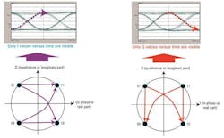
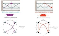
In Figure 1 you can see in the Q eye diagram in purple a transition from '0' to '1' and for I in red a transition from '1' to '0'. As I and Q component are decoupled, we cannot project this information to a symbol transition in the IQ-diagram without ambiguity. The left example could be a transition from '01' or from '00' to '11' or to '10', so four possible transitions are under consideration. The same can be noted when trying to map the Q-transitions.
Such ambiguity may not necessarily create a problem. But here you can also see a distortion in the IQ plot that is not reflected in the two separate eye diagrams. In Figure 1, the bent diagonal transitions in both IQ plots point to a timing skew between the I and Q paths of the modulator. The I is obviously before the Q, which cannot be seen in the two eye diagrams.
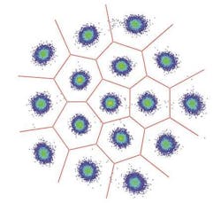
For more advanced formats things get even more complicated. Look at Figure 2 with a special 16-QAM format. How would we map this to eye diagrams?
The figure also reminds us that in complex modulation the decision on which bit sequence we received is made in the IQ plane. So it makes much more sense to judge quality in the same picture. After all, we saw already that some distortions are more visible in this view.
Error vector magnitude (EVM)
Here again we learned from the RF community, where this problem was solved years ago with the intuitive approach of taking the distance of a measured point from the closest ideal constellation point. This concept leaves no ambiguity and works for any modulation format that can be presented in a constellation diagram.
Figure 3 illustrates this for one measured point. The error vector magnitude EVM[n] is the Euclidean distance between the measured point and the ideal reference point:
where n is the symbol index and Ierr = IMeas – IRef and Qerr = QMeas – QRef .
The normalized root mean square average EVM is defined as:
where N is the number of measured points taken into account for calculating the EVMrms. The division by the magnitude of the peak reference vector serves for normalization. Other definitions use the average magnitude of all reference vectors or also the average power. This may be a trap when trying to compare EVM values.
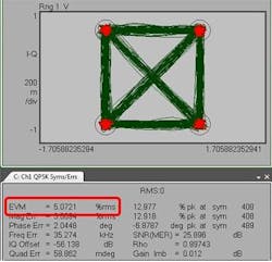
In the example QPSK signal shown in Figure 4, the measured red dots around the four constellation points result in 5% error vector magnitude.
Signal to noise ratio (SNR)
From the EVM, we can also derive the signal to noise ratio (SNR) - also called modulation error ratio (MER). It is the ratio of average symbol power of the transmitted signal to noise power - which includes any term that causes the symbols to deviate from their ideal state:
BER estimation
For the case where we only have Gaussian noise, we can predict the BER from the EVM directly. If the EVM does also contain contributions from other distortions, the prediction becomes more complicated. The measured BER does not increase as much as predicted if we use the simple model, hence the predicted BER provides an upper limit. This is quite obvious for the case where the signal does not contain any noise but the constellation is distorted. In that case we will have a certain value of EVM and hence the predicted BER will be non-zero; however, the actual number of bit errors may be zero.
Get a bigger picture from the EVM
So far, we only investigated the EVM at the symbol times. Looking at the transitions in the IQ plots and plotting EVM versus time or frequency can help to find the root causes of distortions.
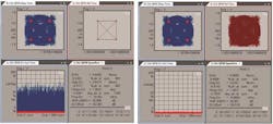
In Figure 5 we see two examples. On the left one, we compare the measured signal to a reference signal of "infinite" bandwidth; on the right side, we compare the same measurement to a reference signal created with a raised cosine filter. Both show the same EVM value at symbol times.
But when you look at the EVM evolution over time, you see the deviation of the measured signal from the "infinite" bandwidth reference signal reflected in high EVM values. If the raised cosine filter used in the transmitter has the same characteristics as the filter used for the reference signal, we see a low EVM also during transition times between the symbols (right side).
Apart from the EVM, there are other error parameters deducible from the IQ plots that help us find the root causes of problems within the optical system.
Gain imbalance
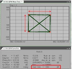
The gain imbalance compares the amplitude of the I signal with the amplitude of the Q signal and is expressed in dB.
In Figure 6 you can see an example of a gain imbalance of about 2 dB, indicating a problem. The I and the Q magnitudes differ by a factor of 1.26.
The gain imbalance could be due to an unbalanced RF drive amplitude from the Mach-Zehnder modulator on the transmitter side.
IQ offset
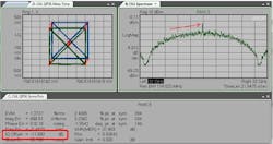
IQ offset (also called IQ origin offset) describes the offset of the constellation diagram from the origin (the ratio of the power at the center frequency to the average signal power.) This data result indicates the magnitude of the carrier feed-through signal. When there is no carrier feed through, IQ offset is zero (-infinity dB). It is given as the ratio of signal to offset:
An IQ offset is often caused by a DC offset either in the I or Q path of the modulator or a small RF drive amplitude and a wrong bias point.
Quadrature error
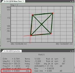
The quadrature error quantifies the aberration from orthogonality between the I and Q quadrature-phase. Ideally, I and Q should be orthogonal (90 degrees apart).
In the case in Figure 8, we observe a quadrature error of almost 10 degrees, which means that I and Q are 80 degrees apart.
A quadrature error usually points to a problem on the transmitter side, where the IQ 90° phase shifter may have the wrong bias point. In this case, also the eye diagram is distorted.
If you adjust the bias voltages of the Mach-Zehnder-interferometer, orthogonality of the I and Q path can be achieved.
Frequency error
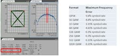
The frequency error shows the carrier's frequency error relative to the local oscillator. This error data is displayed in Hertz and is the amount of frequency shift that the instrument must perform to achieve carrier lock. The maximum frequency error that can be compensated is dependent on the used modulation format (compare Figure 9).
IQ magnitude error
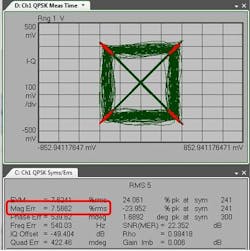
The IQ magnitude error is the difference in amplitude between the measured signal and the ideal reference signal (compare Figures 3 and 10):
Low frequency intensity noise from the transmitter laser, for example, can cause a magnitude error.
IQ phase error
The phase error is the phase difference between the ideal IQ reference signal and the IQ measured signal measured at the symbol time (see Figure 3):
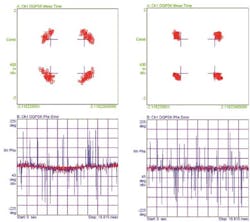
A possible root cause is the signal source, e.g., if you use a DFB laser that has a broader spectrum than an external cavity laser (2-3 MHz vs. 0.1 MHz), this will be reflected in the constellation diagram in an increased phase error (as can be seen in Figure 11). The constellation points that you get with the external cavity laser as a signal source show white Gaussian noise. The phase noise over time is almost zero.
More insight by investigating the IQ diagrams
All the above error parameters show how in coherent optical data transmission IQ diagram analysis provides in-depth insight into the quality of the observed signal.
We were only able to cover the pure errors. It is worth having a look at a whole series of mixed phenomena that can be observed in the IQ diagrams to enable root cause analysis of problems within the optical system. This will be covered in the next article.
Figures are contributed by Oliver Funke, Stephanie Michel, and Bernd Nebendahl.
Stephanie Michel is technical marketing engineer in the Digital Photonic Test Division of the Electronic Measurements Group at Keysight Technologies Inc.
