Advances in data communications receiver design have led to important changes in transmitter characterization and measurement methods for 100G and 400G standards. Both IEEE and OIF-CEI have introduced the concept of replacing many of the historical methods of compensable intersymbol interference (ISI) jitter analysis with a technique of comparing the actual averaged pulse response determined from the transmitter to an extracted linear model. This technique uses a linear fit pulse peak and where the extracted pulse response is leveraged to perform the signal to noise and distortion ratio (SNDR).
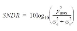
With SNDR, the imperfections of the signal, noise, and distortion are summed and their amplitude (RMS) is compared to the size of the signal. SNDR is less sensitive to ISI caused by factors such as insertion loss and reflections, and ISI can be compensated by equalizers in Tx and Rx. But SNDR includes all other sources of transmitter noise and distortion. A result above 27 dB is a pass in today’s electrical backplane standards (25 Gbps NRZ KR4) and 26 dB for electrical cables (25 Gbps NRZ CR4). For PAM4 this result needs to be even higher. For example, 200GBASE-KR4 requires SNDR ≥ 32.5 dB.
The advantage of SNDR is it offers designers flexibility in how they may reach conformance with several degrees of freedom and permits a strategy of compromise in one specification, while overdriving another to compensate. For silicon evaluators, it’s advantageous to see a single figure of merit, which is a composite of many silicon sub-specifications, when it comes to determining the best device.
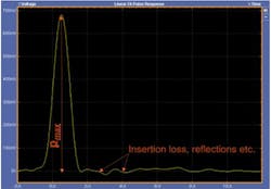
In an SNDR model, the degree that the actual pulse response matches a linear fit model (Figure 1) is the main consideration. The ISI jitter/noise is 100% compensable by equalizers and of no real consequence to the system performance (assuming the equalizers can be implemented in the system). The residue from the linear fit is called distortion. The ratio between the signal from linear fit and distortion-plus-noise projects the system performance with equalizers.
The standard deviation of the error in this model fit is called distortion, the se parameter in the SNDR expression. For each of the four symbol levels, the vertical signal noise is determined at a fixed low-slope point in a long consecutive run of identical PAM4 symbols. The noise parameter sn is the average of the standard deviations of these four symbol measurements. Pmax is the peak amplitude of the pulse response from the linear fit.
There are three residual jitter specifications, JRMS, J5, and even-odd jitter. These are random and high-probability deterministic components that cannot be extracted from the linear pulse modeling process. This is why they stand alone as the only electrical jitter specs in current 400G systems. The reliance on an accurate linear pulse extraction and its analysis make SNDR the single most important measurement in modern data communications systems.
SNDR and instrumentation
There are several key instrument considerations to account for when performing SNDR measurements.
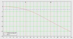
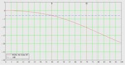
The instrument (signal acquisition) bandwidth for IEEE 802.3bs/cd requires a 33-GHz system, with a response following a fourth order Bessel-Thomson response. The flat group delay or linear phase of this filter is key to minimizing instrument-induced ISI. There are several views on how far past the -3 dB point of the Bessel-Thomson curve the instrument bandwidth needs to support.
Figure 2 shows the 33-GHz Bessel Thompson response required by the IEEE specs in the 100G space, while in Figure 3 the OIF-CEI community has a slightly higher bandwidth spin on this at 40 GHz. In the latter case, the Bessel Thompson profile is carried out to -10 dB, which requires a 56-GHz instrument.
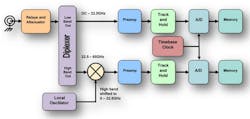
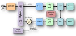
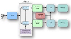
Whether -6 dB or -10 dB is selected as the cutoff point for analysis, there are important noise considerations that factor into the SNDR measurement system. Modern high-bandwidth instruments achieve their target specs through a variety of signal block conversion methods, including asymmetric as shown in the circuit diagram in Figure 4 and asynchronous in Figure 5.
One of the most important factors when considering signal acquisition techniques is the phase linearity of acquisitions across the entire analysis band in addition to the magnitude flatness.
The use of the mixing concept in conventional asymmetric interleaving methods introduces a significant non-linear component at the principal heterodyne junction of the block conversion process. In this architecture, the local oscillator frequency equals the mid-band of the analog front-end bandwidth, which makes it possible to acquire the upper half of the scope passband with one analog-to-digital converter (ADC) and the lower half of the passband with another ADC. The total waveform is then stitched by a digital signal processor (DSP). This architecture requires accurate and stable calibration to achieve and maintain the overall phase linearity.
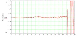
Asynchronous acquisition technology, on the other hand, avoids the use of asymmetric mixing techniques. With this architecture, a pre-sampler is used as a harmonic mixer. The signal paths are symmetrical, and there are no significant differences in propagation delay or phase shift between the two sides of the acquisition channel. This results in the flat phase response shown in Figure 6 from DC to 70 GHz.
This flat response is key to jitter decomposition when PAM4 spectral components are analyzed, which permits low jitter noise floors (e.g., 40 fs RMS). This jitter precision is crucial to minimizing the SNDR se parameter.
Noise Levels
The other important attribute of ATI based acquisition is that its dual and symmetric acquisition system reduces noise by a factor of sqrt(2) compared to conventional asymmetric interleaving.
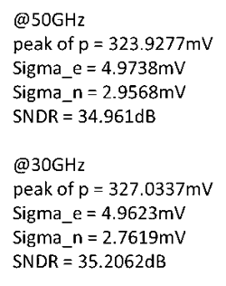
Acquisition bandwidth choices also influence the SNDR sn noise parameters. Not surprisingly, a very high bandwidth system will integrate more noise across its wider passband than a lower bandwidth system. The following examination of SNDR at different acquisition bandwidth figures illustrates this point:
However, with a higher sample rate, it is possible to use a bandwidth limit filter to reduce the scope noise and improve the accuracy of sn measurement.
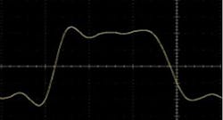
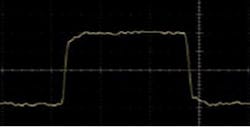
Breaking down these values offers a comprehensive view on how the components of SNDR are influenced by key instrument properties. Intuitively, the Sigma_n (sn) value is reduced with a lower instrument bandwidth, as the noise integration region is reduced by 40% when operating at 30 GHz compared to 50 GHz. Bandwidth limiting can be an effective (but dangerous) method of improving SNDR results. Higher scope bandwidth means that more signal harmonics are available for investigation compared to lower bandwidth instruments. Less intuitively, the pulse peak value may be increased at lower bandwidths.
Figure 7 illustrates the limited harmonic content of a square wave at 30 GHz, with ringing causing higher than expected peak pulse amplitude. In Figure 8 however, at 50 GHz there is sufficient harmonic content to define the true pulse edge with no overshoot or ringing. This results in a lower (but more accurate) pulse peak value.
More accurate SNDR testing
SNDR has emerged as the most important measurement for evaluating electrical 100G and 400G transmitters, yet poses a significant challenge for many classes of test instrumentation. SNDR se is affected by instrument phase linearity and jitter noise floor. SNDR sn is impacted heavily by instrument contributed acquisition noise and needs to be weighed against instrument bandwidth. Fourth order Bessel-Thomson acquisition systems with roll off characteristics above 50 GHz are required to properly characterize true pulse peak values.
John Calvin was formerly the datacom solutions manager at Tektronix. He is a senior member of IEEE and has spent many of this technical years at Tektronix, enabling high-performance communications and consumer/enterprise datacom standards. He holds a Bachelor’s Degree in Electrical Engineering from Washington State University and holds eight patents in measurement-related technology. He is a recognized spec contributor to the fields of InfiniBand, Fibre Channel, PCI Express, SATA, and USB. Early in John’s career he led physical layer design efforts for ITU-T communications standards and has returned to this and recent IEEE 802.3 efforts as an area of professional focus.
Kan Tan is a principle engineer at Tektronix. He has worked on DSP for performance real-time scopes; serial data link analysis including equalizers, channel embed/de-embed; signal integrity analysis such as jitter and noise analysis, PLL and BER estimation; and scope signal path calibrations. He holds 21 patents. Co-authored a book chapter. He received a Ph.D. in Control Systems from University of Houston.
