As fiber to the home (FTTH) deployments with GPON continue at an ever-increasing rate, the constantly growing demand for internet video streaming has service providers already conducting trials of 10G-PON, with plans for deployment imminent. Various standard bodies (ITU, FSAN, IEEE) have adopted their own PON standards. The International Telecommunications Union (ITU) published the GPON standards between 2003 to 2009 (ITU-T G.984.3) but, recognizing the continued demand for network speed would only continue to grow, added the 10G XG-PON standard (ITU-T G.987) in 2010. Existing GPON networks can usually be upgraded to overlay XG-PON transmission on the same physical plant; however, the system polarization-mode dispersion (PMD) limitation will ultimately define the maximum physical distance.
In an effort to further extend the reach for GPON beyond PON optical distribution network (ODN) limits, ITU G.984.6 approved the addition of reach extenders or RE (optical amplifiers or repeaters). An RE can be inserted mid-span between the optical line terminal (OLT) and ODN. The section between OLT and RE is called the optical trunk link (OTL), which extends the total physical plant between the OLT and optical network unit (ONU) to 60 km. Unfortunately, pre-existing GPON testers will not be able to test networks with 10G-PON transmission.
What is PON?
A passive optical network (PON) is the section of a communication network that includes everything between two active elements: the OLT and the ONU/ONT. A PON uses optical wavelength-division multiplexing (WDM) so a single fiber can be used for both downstream and upstream transmission to support quad-play services: data, IPTV, voice, and security.
The OLT broadcasts the same data to all ONUs/ONTs. An ONU/ONT can recognize any data specifically targeted for it by filtering data using ONU-ID (Alloc-ID). Since all active ONU/ONT upstream signals transmit at 1310 nm, a time-division multiplex (TDM) format must be used to manage and grant timeslots in which each ONU/ONT is allowed to transmit to the OLT. The OLT determines the distance and time delay of each subscriber. Then the total available bandwidth is divided between all ONUs so each user only gets a fraction. The upstream transmissions, via burst-mode operation, are allocated on an as-need basis by the OLT for each ONU/ONT that needs to send data. Because the TDM method involves multiple users on a single transmission, the actual upstream data rate is always less than the maximum available bandwidth due to sharing.
The typical split of a single fiber (PON port) is 1:32 or 1:64. A PON port therefore can service up to 32 or 64 subscribers. The maximum number of subscribers can be 16,384, which equates to 32 PON ports using a 1:64 split. On rare occasions, a split ratio of up to 1:128 is used. To provide service over a larger geographical area, the PON can also be deployed with a cascaded split (ex: 1x4 followed by 1x16 split).
GPON
GPON specifies downstream transmission at 1490 nm will be 2.488 Gbps and upstream transmission at 1310 nm will be 1.244 Gbps. IPTV can be transmitted using 1490 nm, but to minimize congestion, some service providers broadcast their video content using RF video (as in RF over Glass, or RFoG) at 1550 nm downstream. When interactive video is required, then a fourth wavelength must be used (1590 or 1610 nm, vendor dependent) for the video return path signal.
As for the data format, the original GPON packets can handle ATM packets directly. Recall that ATM packages everything in 53-byte packets with 48 bytes for data and 5 bytes for overhead. In 2008, the GPON standard removed direct ATM and only called for the use of a generic encapsulation method (GEM) frame to carry protocols. GEM can encapsulate Ethernet, IP, TCP, UDP, T1/E1, video, VoIP, or other protocols as called for by the data transmission.
The GPON network must be tested to verify levels and that reflectance does not exceed system limits:
- Span length must be < 20 km (Class C+ < 60 km) and the span loss budget must be met.
- A fiber scope must be used to inspect connectors and ensure they are free of contaminants, dents, and scratches. Use cleaning tools to clean contaminants. Dents or scratches can create insertion loss and reflectance.
- Downstream and upstream launch power must meet specifications.
- A PON meter must be used to confirm signal levels are acceptable per standards.
There are three primary classifications for GPON are Class A, B or C (see Table 1).
10G-PON Upgrade Path
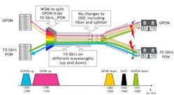
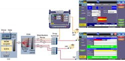
10G-PON (also known as XG-PON G.987) may be the logical next-generation deployment strategy, but today one can choose XG-PON or XGS-PON (G.987.2 and IEEE 802.3 physical layer standards) as an intermediate step to reach multiwavelength NG-PON2 (G.989.3). The XG-PON network architecture can consist of a single passive optical distribution segment (ODS) or a group of passive ODSs interconnected with reach extenders (REs). The optical configuration for XG-PON enables the co-existence of GPON and 10G-PON transmissions using WDM filters and additional bandpass filters (Figure 1).
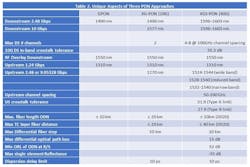
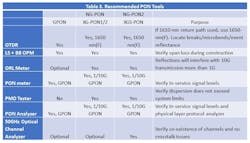
NG-PON2, developed by ITU in 2015, defines a PON architecture capable of supporting total network throughput of 40 Gbps using four symmetric upstream/downstream wavelengths available to each subscriber. The NG-PON2 standard is unique in its use of active tunable filters and a tunable laser in the ONU. XGS-PON is a subset of the NG-PON2 standard; for TWDM-PON within NG-PON2, the eight-channel wavelengths are defined. The table below highlights some of the unique aspects of the PON networks.
The debate over the best architecture to deploy for 10G-PON remains ongoing, but for the U.S. market, it appears that XGS-PON may be winning the battle at the moment.
PON Testing
In the past, some companies installed GPON networks using pre-existing construction tools such as OTDRs, light sources, and traditional broadband power meter. GPON infrastructures are less forgiving than 10G-PON, so this practice is not recommended for the following reasons:
- upstream traffic is “bursty in nature” and cannot not be tested unless the ONU is authorized by the OLT downstream traffic
- broadband meters (InGaAS) are not pass-through meters and do not contain filters to isolate specific transmissions. On a WDM network, total transmission span power will be measured regardless of user wavelength settings.
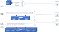
In Figure 2 below, we illustrate how a broadband optical power meter (OPM) differs from a GPON and XG-PON meter:
As you can see, broadband OPMs are useful during the construction of a PON network, but once the network is in service, this type of basic meter is not practical. A GPON meter is a pass-through meter that has WDM/filters and dedicated receivers for each transmission wavelength. Using this type of meter, a technician is able to check all transmission levels (1310/1490 and optionally 1550 nm) prior to new service activation. For GPON networks that have RF overlay and need a return-path wavelength checked, one could use a broadband OPM provided you check the set-top box signal before it is merged into the ONU. To test 10G-PON, not only must we add additional receivers, to ensure no crosstalk exists, we must also incorporate band-pass filters, not just WDM to provide the necessary isolation for 1550- and 1577-nm transmission.
PON test tools are categorized as physical layer or higher-layer tools. The following test tools are recommended to diagnose faults between the OLT and ONU/ONT:
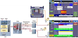
Physical Layer Field Tools (see Figure 3)
- Optical time-domain reflectometer (OTDR) with 1625- or 1650-nm filtered testing, to diagnose faults without disrupting service.
- Optical power meter (broadband or PON) and light source to measure span budget and OLT/ONT transmission power.
- Optical return loss (ORL) meter to test span return loss.
Higher Layer Tools (Figure 4)
- Polarization mode dispersion (PMD) tester to verify dispersion is within system limits.
- PON Analyzer to troubleshoot alarms/errors at the customer premises and monitor PLOAM and OMCI messages between the OLT and ONU.
- Optical channel analyzer to verify co-existence of GPON and XG-PON downstream signals and identify potential crosstalk issues.
The table below summarizes the difference in tools recommended to ensure successful upgrade from GPON to 10G GPON.
While one can certainly argue about the cost/benefit of outfitting fields technicians with all the tools shown above, one cannot argue with the fact that 10G-PON will eventually make GPON test sets obsolete. So when budgeting for a 10G-PON upgrade, don’t forget to budget for new tools to support your 10G upgrade endeavors.
References:
- ITU-T G.984.2 (03/2003) Gigabit-capable Passive Optical Networks: Physical Media Dependent layer specification
- ITU-T G.984.2 Amendment 1(02/2006) New Appendix III – Industry best practice for 2.488 Gbit/s downstream, 1.244 Gbit/s upstream GPON
- ITU-T G.984.2 Amendment 2(03/2008)
- ITU-T G.987.2 (02/2016) 10-Gigabit-capable Passive Optical Networks (X GPON): Physical media dependent layer specification
- ITU-T G.989.2 (01/2010) 40-Gigabit-capable Passive Optical Networks 2 (N GPON2): Physical media dependent layer specification
- ITU-T G.989.2 Amendment 1 (04/2016) 40-Gigabit-capable Passive Optical Networks 2 (N GPON2): Physical media dependent layer specification
Nancy Lee is senior product manager of optical products with VeEX Inc. She has 30 years of experience in the telecommunications industry with emphasis in test and measurement. She has aided service providers with network upgrade procedures including AT&T Mobility’s implementation of fiber to the antenna (FTTA) test solutions; written test methods and procedures for Verizon Wireless, and guided numerous carriers with fiber characterization of legacy fiber plant for support of 10G or higher data rates. In addition to VeEX, Nancy has worked with Anritsu, NetTEST, Acterna and JDSU (now Viavi Solutions) in various sales and marketing roles.
