Calculating statistical confidence levels for error-probability estimates
How can you be sure that your design meets the required reliability specs? These steps will steer you in the right direction.
JUSTIN REDD, Maxim
Many components in digital-communication systems must meet a minimum specification for the probability of bit error (P(e)). For a given system, P(e) can be estimated by comparing the output bit pattern with a predefined pattern applied to the input. Any discrepancy between the input and output bit streams is flagged as an error, and the ratio of detected bit errors (e) to total bits transmitted (n) is P(e), where the prime character signifies an estimate of the actual P'(e). The quality of this estimate improves with the total number of bits transmitted. The relationship can be expressed as:It is important to transmit enough bits through the system to ensure that P'(e) is a reasonable approximation of the actual P(e) (i.e., the value to be obtained if the test could proceed for an infinite amount of time). For a reasonable limit on test time, therefore, we must know the minimum number of bits that yields a statistically valid test.
In most cases, it is sufficient to prove that P(e) is less than some upper limit (versus proving its exact value). For example, the P(e) required by many telecommunications systems is 10-10 or better (meaning that it must be less than or equal to the upper limit of 10-10). The primary advantage of associating a confidence level with an upper limit on P(e) is that test time can be reduced to the minimum possible while maintaining any selected level of confidence in the test results.
Statistical confidence level is defined as the probability, based on a set of measurements, that the actual probability of an event is better than some specified level. (For the purpose of this definition, actual probability means the probability that is measured in the limit as the number of trials tends toward infinity.) When applied to P(e) estimation, the definition of statistical confidence level can be restated as the probability (based on (detected errors out of n bits transmitted) that the actual P(e) is better than a specified level g (such as 10-10). Mathematically, this can be expressed as:where P[ ] indicates probability and CL is the confidence level. Because confidence level is a probability by definition, the possible values range from 0% to 100%.
After computing the confidence level, we can say we have CL percent confidence that the P(e) is better than g. As another interpretation, if we repeat the bit-error test many times and recompute P'(e) = e/n for each test period, we expect P'(e) to be better than g for CL percent of the measurements.
Calculations of confidence level are based on the binomial distribution function described in many statistics texts M.1,2 The binomial distribution function is generally written as:Equation 3 gives the probability that k events (i.e., bit errors) occur in n trials (i.e., n bits transmitted), where p is the probability of event occurrence in a single trial (i.e., a bit error) and q is the probability that the event does not occur in a single trial (i.e., no bit error). Note that the binomial distribution models events that have two possible outcomes, such as success/failure, heads/tails, or error/no error. Thus, p + q = 1.
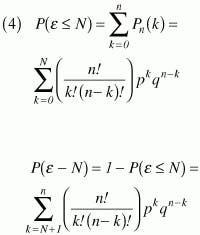
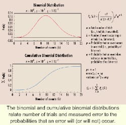
When we are interested in the probability that N or fewer events occur in n trials (or, conversely, that greater than n events occur), then the cumulative binomial distribution function of equation 4 is useful:Graphical representations of equations 3 and 4, along with some of their properties, are summarized in Figure 1.
In a typical confidence-level measurement, we start by choosing a satisfactory level of confidence and hypothesizing a value for p (the probability of bit error in transmitting a single bit). We represent the chosen p value as ph. In general, we choose these values according to a limit imposed by specification (e.g., if the specification is P(e)10-10, we choose ph= 10-10 and a confidence level of, say, 99%).We can then use equation 4 to determine the probability P(e>N ph), based on ph, that more than N bit errors will occur when n total bits are transmitted. If, during actual testing, less than N bit errors occur (even though P(e>N ph) is high), then one of two conclusions can be made: (a) We just got lucky or (b) the actual value of p is less than ph. If we repeat the test over and over and continue to measure less than N bit errors, then we become more and more confident in conclusion (b).
The quantity P(e>N ph) defines our level of confidence in conclusion (b). If ph = p, we have a high probability of detecting more bit errors than N. When we measure less than N errors, we conclude that p is probably less than ph, and we define as the confidence level this probability that our conclusion is correct. In other words, we are CL% confident that P(e) (the actual probability of bit error) is less than ph.
In terms of the cumulative binomial distribution function, the confidence level is defined as:where CL is the confidence level in terms of percent.
As noted above, when using the confidence-level method we generally choose a hypothetical value of p (ph) along with a desired confidence level (CL), and then solve equation 5 to determine how many bits (n) we must transmit through the system (with n or fewer errors) to prove our hypothesis. Solving for n and n can prove difficult unless approximations are made.
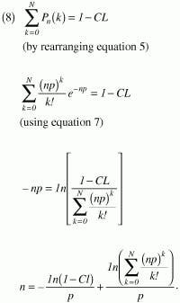
If np is >1 (i.e., we transmit at least as many bits as the mathematical inverse of the bit-error rate), and k has the same order of magnitude as np, then the Poisson theorem1 (equation 6) provides a conservative estimate of the binomial distribution function:Note that the second term in equation 8 equals zero for N = 0, and for that case, the equation is easily solved. Solutions to equation 8 are more difficult for N >0, but they can be obtained empirically using a computer. We can now determine the total number of bits that must be transmitted through the system to achieve a desired confidence level. Following is an example of this procedure:
- Select ph, the hypothetical value of p. This value is the probability of bit error that we would like to verify. For example, if we want to show that P(e)<10-10, then we set p in equation 8 equal to Ph = 10-10.
- Select the desired confidence level. Here, we are forced to trade confidence for test time. To minimize test time, choose the lowest reasonable confidence level. The tradeoff between test time and confidence level is proportional to -ln(1-CL).
- Solve equation 8 for n. In most cases, this task is simplified by assuming that no bit errors will occur during the test (i.e., N = 0).
- Calculate the test time. The time required to complete the test is n/R, where R is the data rate.
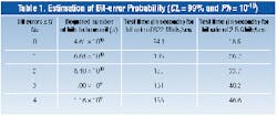
To develop a standard P(e) test for the MAX3675 and MAX3875, we might select the test time corresponding to N = 3 from Table 1. Using a bit-error-rate tester (BERT), we transmit 1011 bits through each of the two chips. The test time for 1011 bits is 2 min and 41 sec at 622 Mbits/sec or 40.2 sec at 2.5 Gbits/sec. At the end of the test time, we check the number of detected bit errors (e). If (e) is <3, the device has passed, and we are 99% confident that P(e)<10-10.
Dan Wolaver has documented a method for reducing test time by stressing the system.3 It is based on an assumption that the dominant cause of bit errors is thermal (Gaussian) noise at the input of the receiver. (Note that this assumption excludes jitter and other potential causes of error.) For systems in which this assumption is valid, the signal-to-noise ratio (SNR) can be reduced by inserting a fixed attenuation in the transmission path (i.e., the attenuation applies to the signal only, not the dominant noise source). In the previous example (MAX3675 and MAX3875), it was determined that jitter effects and nonlinear gain in the input limiting amplifier violated the key assumptions of this method, so it was not employed.
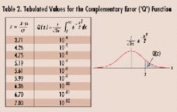
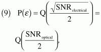
In systems where the assumption is valid, the probability of bit error can generally be calculated4,5 as:where Q(x) is the complementary error (or the Q function included in many communications textbooks6). A variety of other sources for this data are available, including the NORMDIST function in Microsoft Excel. Key values for the complementary error function are listed in Table 2.
Equation 9 shows that the probability of bit error increases as the SNR decreases. If a fixed attenuation (a) is inserted in the transmission path, then the signal power (PS) is reduced by the factor a, while the noise power (PN) is unchanged. The SNR is therefore reduced from SNR = PS/PN to SNR = PS/aPN. The corresponding P(e) is increased by a factor that can be calculated using equation 9 and Table 2.
We can now repeat the test method outlined previously, using a modified value for ph. The calculation can then be extrapolated to any other SNR by using equation 9. The result is the same, but the test time may be significantly shorter.Table 3 (vs. Table 1) illustrates the reduction in test time achievable using an optical signal-attenuation factor of a = 1.132, which reduces the SNR from 12.7 to 11.2. In this example, ph is increased from 10-10 to approximately 10-8 (calculated using equation 9). This factor-of-100 increase in ph results in a corresponding decrease in test time. Extrapolation of the results in Table 3 to other SNRs retains the same confidence level of 99%.
Statistical confidence levels can be used to establish the quality of an estimate. Application of this idea allows a tradeoff of test time versus the level of confidence desired in the test results.
Justin Redd, Ph.D. E.E., is a senior member of the technical staff for the high-frequency/fiber communications group at Maxim Integrated Products (Beaverton, OR).
- A. Papoulis, Probability, Random Variables, and Stochastic Processes, New York, McGraw-Hill, 1984.
- K.S. Shanmugan and A.M. Breipohl, Random Signals: Detection, Estimation, and Data Analysis, New York, John Wiley and Sons, 1988.
- D.H. Wolaver, "Measure Error Rates Quickly and Accurately," Electronic Design, pp. 89-98, May 30, 1995.
- J.G. Proakis, Digital Communications, New York, McGraw-Hill, 1995.
- J.M. Senior, Optical Fiber Communications: Principles and Practice (second edition). Englewood Cliffs, NJ, Prentice Hall, 1992.
- B. Sklar, Digital Communications: Fundamentals and Applications. Englewood Cliffs, NJ, Prentice Hall, 1988.


