These buffer tubes use various materials and techniques to protect cables from being damaged by water and other environmental factors.
DR. ROBERT IMES, MEYER ROSEN, and KENNETH PRICE, Ticona
Loose buffer tubes house and protect optical fibers in long-distance terrestrial, undersea, and aerial cables. They form an inner barrier to water penetration and help isolate the fibers from vibration and thermal extremes. Cables can have as many as 24 color-coded buffer tubes, each containing up to 12 fibers.
The polymer used for buffer tubes has evolved from fluoropolymer to nylon-12 to polybutylene terephthalate (PBT), which came into commercial use in the 1980s. Tubes in some terrestrial cables are made of polypropylene (PP), which has a modest cost advantage over PBT.
Loose buffer tubes usually contain a water-blocking gel to impede water penetration. Polybutene gels, generally added in PBT tubes, cannot be used with PP because they strip out the antioxidants added to PP to prevent embrittlement. As a result, PP buffer tubes require more expensive silicone gels. Instead of an internal gel, some cables contain PP tubes wrapped in an absorbent polymer tape, which swells to create a seal when wetted.
PBT is a widely used loose buffer-tube material because it works well across a wider range of conditions and has better mechanical properties than PP. For instance, PBT provides greater creep and crush resistance in aerial cables than PP. It also is the primary choice for submarine cables because of its long history of dependable performance in the marine environment. However, as we will discuss, manufacturing processes can have a significant impact on the performance of these tubes.
During the extrusion of a loose buffer tube, gel and an optical fiber bundle pass through the center of a die as the tube is formed around them. The hot tube, pulled by downstream take-up equipment, draws down onto the gel-fiber combination and is then cooled. Final tube diameter varies with the number of fibers enclosed, but is typically 2 to 2.5 mm. It usually has a wall thickness of 0.4 mm. PBT and PP tubes can be made on the same equipment. Less tension should be applied to PP tubes, however, because PP can cold draw and change dimension after it solidifies.PBT buffer tubes leave the die at about 250°C (482°F) and are quenched in a series of water baths zoned to step temperature down low enough so the tubes do not flatten when wound. A four-bath setup may involve two baths, rollers with a water spray, and two final tanks.
Quality control is essential in this process, because the tube must be free of flaws that might interfere with cable performance. Online measuring systems typically define outside and inside diameters and look for lumps, bumps, and other irregularities. In addition, a system that electronically links the speeds of the extruder and take-up equipment controls draw-down.
Variables affecting buffer-tube quality include the properties of the PBT, die configuration, initial quench bath temperature, and the tension applied to the tube. Those show up in a number of tube factors, such as tube diameter, excess fiber length, postproduction shrinkage, and embrittlement.
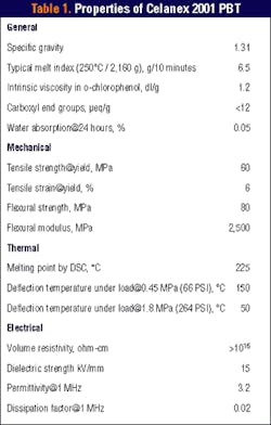
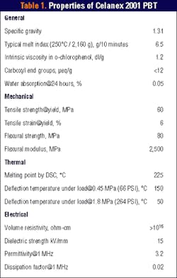
The plastic used must be highly consistent and meet tight specifications. One buffer-tube polymer (Celanex 2001 PBT), for instance, has a melt index range of 6 to 8.5 and a maximum carboxy end group (CEG) of 12 (see Table 1). The narrow melt index range fosters tube consistency over long production runs. The magnitude of the melt index provides sufficient melt strength so the tube stays round after it leaves the extruder and before it solidifies.
The low CEG, a factor not specified in most PBT applications, minimizes hydrolysis during extrusion. Hydrolysis shortens polymer chains, causing them to lose elongation and tensile and impact strength. Manufacturers usually check hydrolysis resistance when starting up a buffer-tube line.The resin must also have a low fines level (usually below 100 ppm). Fines are often PBT particles abraded off pellets during handling, so manufacturers are advised to limit fines generation by, for instance, using dense phase rather than dilute phase conveying. In addition, the polymer should be dried to a water content of 0.02% or less before extrusion. That is often done by heating at 121°C (250°F) for four hours in an online dehumidifying dryer just before processing.
A PBT's viscosity determines how fast it can pass through the die. If extrusion speed is too great, the flow grows unstable and problems such as surface roughness, alligatoring, and variations in wall thickness can occur. As line speed rises, dies need larger gaps so more material can flow through.
Loose buffer tubes are configured so optical-fiber length is about 0.01% longer than the surrounding tube. This excess length lets fibers follow smooth curves around bends and allows the tube to shrink as temperature drops without forming microbends in the fibers that can attenuate signals.
This carefully controlled relationship between tube and fiber length can be upset if the tube is not properly heat set after draw-down. When the tension on the tube that causes draw-down is released, the extended polymer chains want to return to a more relaxed state but are frozen in place as the polymer solidifies.
When such orientation stress exists, the polymer may relax and shorten the tube after installation in the field if the cable is heated above PBT's glass transition temperature (Tg), i.e., about 40° to 45°C (104° to 113°F). That can occur in aerial cables exposed to daily or seasonal thermal cycling.
The change in length due to relaxation could be an order of magnitude greater than that allowed for in excess fiber length. Since the buffer tube is typically bound into the cable by friction, such shrinkage is usually seen in the last meter or so before a terminus.
Another source of tube shrinkage relates to PBT's semicrystalline nature. The crystals that form as PBT solidifies from the melt occupy less room than the amorphous melt, so the polymer contracts somewhat in the process. If there is not enough time for crystals to form fully before the tube solidifies, crystallization can continue in the field if temperature goes above Tg. Tube shrinkage due to poor crystallization is much less frequent than that due to relaxation of the polymer.
Postproduction length changes related to draw-down and crystallization can be minimized by holding the initial quench bath well above Tg, i.e., 50°C (122°F) or greater. That allows molecules to relax while under tension so they won't realign later and also allows for crystallization to be completed. The added crystallization reduces the number of amorphous regions that can harbor residual stresses and lead to tube failure.
A Ticona laboratory study found that an initial quench bath temperature of 70°C (158°F) eliminates all postproduction shrinkage at room temperature and minimizes length change even after exposure to a temperature of 80°C (176°F) (see Table 2).
Draw-down ratio compares the diameters of the die opening and the finished tube. (It sometimes is defined as the tube's cross section before and after draw-down.) The ratio is a function of how fast the tube is extruded and how fast it is pulled downstream. Higher line speeds call for higher draw-down ratios. That occurs because higher speeds require dies with larger openings, so draw-down must be greater to reduce tube diameter to the desired size.
Draw-down ratio affects the inside and outside diameters of a tube and has a major effect on shrinkage. The lower the draw-down ratio, the less stress is placed on the polymer and the less the potential for shrinkage.
Buffer-tube production speeds, typically near 200 mpm today, are being pushed to 250 mpm or greater. While it is possible to boost the speed of an existing buffer-tube line using a specific PBT resin, there is a limit to how high that can go.
To increase line speed significantly, manufacturers must alter the entire line. The fiber-feed mechanism and gel pump must be upgraded to the new speed. The extruder needs a screw that feeds at a higher rate and a barrel that can remove the heat generated by the higher shear level.
Changes downstream of the extruder include adapting quench bath temperature and residence time so the tube cools properly and installing faster take-up equipment.
Increasing speed to 250 mpm also calls for use of a lower-viscosity PBT. New PBT grades with melt indexes in the 9 to 15 range have become available to accommodate higher line speeds with no loss in hydrolysis resistance and with minimal shrinkage.
Dr. Robert Imes is a staff chemist, Meyer Rosen is a product specialist, and Kenneth Price is polyester product manager, general industries, at Ticona (Summit, NJ).
Post-extrusion shrinkage of loose buffer tubes increases with increasing draw-down ratio and line speed and decreases with increasing quench bath temperature. General guidelines for producing high-quality buffer tubes include:
- PBT melt temperature should be 250 to 260°C
- Dry PBT at least four hours at 125°C
- Keep line speed as low as production demands allow
- Keep draw-down ratio as low as line speeds allow
- Hold bath temperature above 50°C, if safety concerns allow
- Allow adequate initial bath length, typically more than 20 ft


