Bias controllers for external modulators in fiber-optic systems
Fiber-optic links are becoming more common for analog functions; bias control can make the difference in meeting performance requirements.
DR. EDWARD ACKERMAN, HAROLD ROUSSELL, and DR. CHARLES COX, Photonic Systems Inc.
The booming telecommunications industry has sought to leverage the attractive features of optical fiber: its small size and weight, low dispersion, and very low attenuation per unit length. These same features render it the ideal medium in which to perform important analog functions such as microwave antenna remoting and true time-delay beamforming.Successful digital or analog fiber-optic link design1 requires an understanding of the impact each component has on the link's performance. We'll look at how the performance of an external modulation link (see Figure 1) is affected by characteristics of the modulator's bias controller.
Currently, two types of external modulators are commercially available and can be considered for use in high-bit-rate digital or high-performance microwave fiber-optic links. In one type, the electro-absorption modulator (EAM), the percentage of photons absorbed in a semiconductor optical waveguide is modulated by varying the strength of the electrical field applied across the waveguide. In a second type, the Mach-Zehnder modulator (MZM), the phase of light in the optical waveguides in an inorganic, semiconductor, or polymer material is modulated, then converted to intensity modulation by interferometrically combining the phase-modulated light with light in the second path of a Mach-Zehnder interferometer.
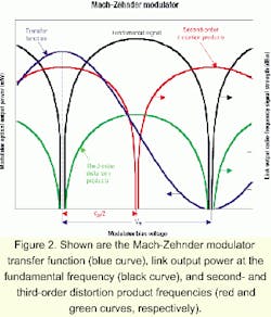
Both the EAM and MZM have points on their transfer function curve (the plot of optical output power versus applied voltage) at which link performance is optimized. In discussing the difficulty of maintaining the optimum modulator bias point as well the consequences of not doing so, we'll provide quantitative calculations only for the case of the MZM. That's because the MZM, unlike an EAM, has a predictable transfer function shape. Our qualitative statements, however, will apply to both the MZM and EAM.The blue curve in Figure 2 shows the transfer function of an MZM. The bias voltage changes the optical phase difference between the interfering waves at the output of the Mach-Zehnder interferometer and thus changes the output intensity. The peaks of the transfer function occur when the phase difference is an integer multiple of 360 degrees (constructive interference), and the nulls occur when the phase difference is an odd-integer multiple of 180 degrees (destructive interference). The MZM's halfwave voltage Vπ is defined as the change in bias voltage necessary to move between a peak and a null on the transfer function curve-in other words, the bias voltage necessary to change this phase difference by 180 degrees (or π radians).
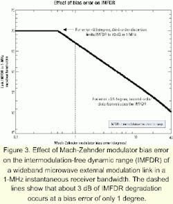
In an analog system that uses an MZM-based fiber-optic link to convey a signal without converting it to a new microwave frequency, the output fundamental signal strength is maximum when the MZM is biased at any voltage that is halfway between a maximum and minimum transmission point on the transfer function curve-a so-called "quadrature" bias point (see Figure 2). Quadrature bias points occur when the optical phase difference at the output of the two paths in the Mach-Zehnder interferometer is an odd-integer multiple of 90 degrees. Maintaining the MZM bias at quadrature is very important in microwave systems with bandwidths wider than one octave, because only at quadrature are second-order distortion products minimized, as Figure 2 shows.Analytical models2 and experimental measurements3 have both shown that for an external modulation link that uses a low-noise continuous-wave laser in conjunction with an MZM at its quadrature bias and a detector operating at a DC photocurrent of 2.5 mA, the link's intermodulation-free dynamic range (IMFDR) is about 70 dB in a 1-MHz instantaneous receiver bandwidth. Failing to maintain quadrature bias can substantially reduce this dynamic range, because the input power level at which second-order distortion products exceed the output noise can lie below the input power level at which third-order distortion products exceed the output noise. Figure 3 shows the IMFDR reduction caused by MZM bias errors of up to 45 degrees off quadrature. Note from Figure 3 that a bias error of even 1 degree reduces the IMFDR by about 3 dB.
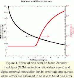
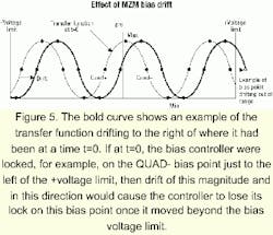
In many digital systems, and in analog systems where frequency conversion is desired, the MZM is biased at either the maximum or minimum transmission point on the transfer function curve rather than at quadrature bias. In a digital link, bias errors result in a degradation of the extinction ratio (the ratio of powers in the "1" and "0" bits), which affects the link's bit-error rate (BER).Figure 5 shows the transfer function of an MZM and how we define four bias points: MAX and MIN, which are self-explanatory, and QUAD+ and QUAD-, which are occurrences of quadrature bias points on the transfer function's positive and negative slopes. Ideally, the desired MZM bias point (i.e., QUAD+ or QUAD- for many analog links and MIN or MAX for many digital links) would occur at a specific DC bias voltage that remains constant for all time despite variations in environmental conditions. Pyroelectric, photorefractive, and photoconductive effects in the MZM's electro-optic material (often lithium niobate, a semiconductor-like gallium arsenide, or an electro-optic polymer) cause the transfer function to "drift" to the left or right-as illustrated by the bold curve in Figure 5-such that a specific DC bias voltage (or even 0 V) may, for example, yield a quadrature point on the transfer function curve at one time and a minimum point on the curve at a later time and/or at a different temperature.
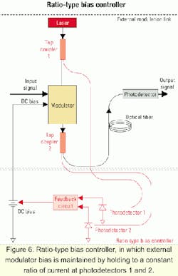
In many fiber-optic link applications, this tendency of MZMs to drift necessitates the use of a bias controller. Figure 6 shows one system configuration for controlling the modulator bias, which we call a ratio-type bias controller. Two tap couplers are used to sample a small percentage of the optical power entering and exiting the modulator. The bias controller consists of photodetectors that convert the tapped modulator input and output light levels to DC current levels and a feedback circuit that adjusts the modulator bias to maintain the desired ratio of photodetector currents.At first glance, a ratio-type bias controller seems like it would perform adequately; however, it has three substantial disadvantages:
- It is expensive, involving two fiber-optic tap couplers (one of which-at the modulator input-needs to operate in polarization-maintaining fiber) and two photodetectors in the bias controller circuitry. Less obvious is the additional cost associated with customizing the feedback circuit to set it to the desired ratio, which depends on the insertion loss of the specific modulator being controlled as well as on the characteristics of the specific tap couplers and photodetectors.
- A more fundamental disadvantage is that a number of factors can change the desired ratio (i.e., the ratio corresponding to the correct bias point). Figure 7 contains plots of two examples showing the bias error that could occur in a ratio-type bias controller due to environmentally induced changes in the insertion loss of the modulator or characteristics of the two couplers or photodetectors.
- A ratio-type bias controller cannot distinguish points on the positive slope of the transfer function curve from ones on the negative slope.
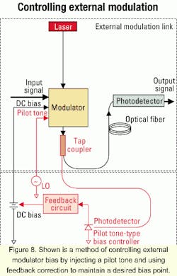
When the desired bias point is a maximum or minimum point (i.e., for digital applications), the photodetected signal is fed to a feedback circuit that continuously adjusts the MZM's DC bias voltage to minimize the signal power detected at the pilot tone frequency. Conversely, when the controller is operated in quadrature mode (i.e., for most analog applications), the photodetected signal is fed to a feedback circuit that continuously adjusts the MZM's DC bias voltage to minimize the detected second harmonic of the pilot tone frequency. The accuracy of this bias control method is unaffected by the small changes in environmental conditions that degrade the ratio-type controller's bias accuracy.
Comparing the phase of the pilot tone at the output of the controller to the phases of the detected pilot tone and its second harmonic distinguishes a QUAD+ from a QUAD- bias point and distinguishes a MAX from a MIN bias point. The ability to distinguish the positive slope of the transfer function curve from the negative slope is another way that the pilot tone-type controller is superior to the ratio-type controller.
A disadvantage of the pilot tone-type bias controller is the possibility that the presence of a pilot tone at the MZM output could degrade the link performance. The pilot tone's effect on a digital link's BER is difficult to specify. In analog links, however, the effect on IMFDR is easy to quantify as a function of the pilot tone strength. The IMFDR can decrease because the third-order nonlinearity of the MZM transfer function results in intermodulation distortion products at two in-band frequencies equal to the desired radio-frequency (RF) signal frequency plus and minus twice the pilot-tone frequency. These distortion products appear at the link output and cannot be filtered out unless the link's operational bandwidth is limited to less than twice the pilot tone frequency.
As mentioned earlier, in the absence of a pilot tone, shot noise and two-tone intermodulation distortion limit the maximum IMFDR of an MZM-based external modulation link to a value of:where ID,max is the DC current at the link's output photodetector when the MZM is biased for maximum transmission, q is the electronic charge, and B is the instantaneous receiver bandwidth. The equation dictates an IMFDR of about 110 dB/Hz2/3 (or 70 dB in 1 MHz) if optical power is supplied to a quadrature-biased MZM, such that the DC photocurrent (which is ID,max/2) is 2.5 mA.
When a pilot tone is present, IMFDR can be further limited by the mixing of an RF tone and the pilot tone rather than by the mixing of two RF tones. Thus, it has been shown4 that the actual link dynamic range is whichever is smaller of what was calculated using the above equation orwhere mPT is the modulation index of the pilot tone (defined as the pilot tone's peak-to-peak voltage divided by the modulator's Vπ. This equation shows that a pilot tone modulation index of 1.6% (for instance) would permit an IMFDR of 70 dB, which is about the limit imposed by the modulator's third-order distortion in a 1-MHz receiver bandwidth.1,2 What prevents the use of such a weak pilot tone? Generally, a stronger input to the feedback circuitry allows the bias controller to achieve greater bias accuracy, acquire the correct bias point more quickly, and react more quickly to phenomena that would otherwise cause the bias point to drift.
Fortunately, the strength of the pilot tone-modulated signal at the photodetector in the bias controller is a function of not only mPT, but also the percentage of light routed to the controller by the tap coupler at the output of the modulator. For example, if the desired acquisition time and degree of bias accuracy can be obtained using a 1% tap coupler and a pilot tone strength of mPT=3%, then the same results can be obtained using a 2% tap coupler in combination with mPT=1.5 %.
As the second equation indicates, the effect of reducing mPT by a factor of two is that the maximum achievable IMFDR is increased by a factor of 16 (~12 dB). The only detrimental effect of using a 2% rather than 1% tap coupler is an ~0.05-dB (=10xlog[99%big Pi98%]) increase in the link's total optical insertion loss. In one commercially available pilot tone-type modulator bias controller, the tap coupling percentage has been increased to permit the use of a weak pilot tone, while still permitting a high degree of bias accuracy (±0.5 degree or better at the QUAD point, and ±0.2 degree or better at the MAX or MIN point).
The issues discussed here have been chiefly dealt with as they apply to MZMs, but the information also applies, at least qualitatively, to other types of external modulators, including EAMs as well as "linearized" modulators, in which the third-order distortion is cancelled using one of a variety of methods.5 That is, if the linearized bias point is maintained using a pilot tone-based feedback circuit, the modulator may generate stronger in-band intermodulation distortion products by mixing the pilot tone with an input RF tone than by mixing two input RF tones, resulting in smaller link dynamic range than what the linearized modulator would otherwise enable.
Dr. Edward Ackerman is vice president of research and development, Harold Roussell is staff engineer, and Dr. Charles Cox is founder and president of Photonic Systems Inc. (Burlington, MA).
- G. Keiser, Optical Fiber Communications, McGraw-Hill, New York, 1983.
- E. Ackerman, S. Wanuga, D. Kasemset, A. Daryoush, and N. Samant, "Maximum dynamic range operation of a microwave external modulation fiber-optic link," IEEE Trans. Micro wave Theory Technology, Vol. 41, pp. 1299-1306, August 1993.
- G. Betts, C. Cox, and K. Ray, "20-GHz optical analog link using an external modulator," IEEE Photonics Technology Letter, Vol. 2, pp. 923-925, December 1990.
- E. Ackerman and C. Cox, "Effect of pilot tone-based modulator bias control on external modulation link performance," Proceedings of IEEE International Topical Meeting on Microwave Photonics (Oxford, UK), pp. 121-124, September 2000.
- U. Cummings and W. Bridges, "Bandwidth of linearized electro-optic modulators," Journal of Lightwave Technology, Vol. 16, pp. 1482-1490, August 1998.


