'Laser-optimized' multimode fiber presents standardized-testing challenges
The advent of the IEEE's 802.3ae 10-Gigabit Ethernet standard has created the need for a new type of fiber, one that is optimized for 850-nm vertical-cavity surface-emitting lasers (VCSELs). The market opportunity for such "laser-optimized" fibers comes with a new set of test issues for manufacturers, specifically, the measurement of differential mode delay (DMD). While many manufacturers previously had measured DMD for process control through a variety of methods, the need for consistent results has led to the creation of standardized test procedures—and left fiber makers with the challenge of adopting these procedures into their production processes. An understanding of DMD, the new test procedures, and production requirements is essential before manufacturers can determine the best test strategy.
During the formulation of the IEEE 802.3z Gigabit Ethernet (GbE) standard, link engineers realized that the bandwidth of a multimode optical fiber, as measured by the fiber manufacturer, was not a reliable indicator of the fiber's actual bandwidth when it was installed in link with a laser-based transceiver. The discrepancy was due mainly to current-generation multimode fibers (MMFs) being designed for use with LED sources, and their bandwidths were characterized in the factory via test conditions that simulated these sources (i.e., overfilled launch). When a small spot laser source such as a VCSEL was used in the field, the fibers were "underfilled"—light was only being launched into a fraction of the fiber's available modes and the fibers performed differently than their factory measurements would have indicated. The resulting unpredictability of the fiber bandwidth led the IEEE to set very conservative maximum link lengths for several MMF types in the GbE standard.
In 2000, the Telecommunications Industry Association (TIA) and International Electrotechnical Commission (IEC) multimode optical-fiber working groups addressed the two main sources of this performance unpredictability. First, they established specifications for VCSEL transceiver launch distribution to ensure greater consistency in what mode groups the source filled. Second, they revised existing multimode bandwidth test procedures to add a new restricted mode launch (RML) test condition for fibers destined for GbE service. The objective of RML was to more closely approximate the new output launch distribution specified for gigabit VCSELs and therefore provide a more realistic fiber bandwidth measurement that would be a more useful predictor of actual system performance.
Unfortunately, these standards were not established until almost two years after the IEEE GbE standard had been approved. However, the knowledge gained by the TIA and IEC task groups proved very useful during the creation of the 802.3ae 10-GbE standard. When the task groups started work on this new project, it was immediately clear that 10-Gbit/sec transmission, even with a shorter target link length of 300 m, represented a more significant challenge than 1-GbE. It was also clear that legacy MMFs such as 62.5-µm FDDI LAN or 50-µm ISO/IEC 11801 premises fibers stood little chance of meeting the new goals. An entirely new MMF type, an 850-nm laser-optimized fiber, would need to be developed.
Group members also realized that even with these new fibers, another version of the RML bandwidth test would not be sufficient to guarantee 10-Gbit/sec, 300-m operation. This combination of speed and distance could only be achieved by reducing the modal dispersion characteristics of the fiber to unprecedented levels, and that was only possible if this dispersion were measured in a more fundamental way. They determined that the DMD of every laser-optimized fiber would need to be measured and that the DMD would need to meet very stringent specifications.
So, what is DMD? One way to look at it is that it is analogous to a pulse delay (time domain) chromatic dispersion measurement. But instead of measuring the propagation delay of a laser pulse as a function of wavelength, the propagation delay of the pulse is measured as a function of the radial position from which the pulse is being launched into the MMF core.Figure 1 provides a simple illustration of a time domain DMD measurement. A probe-laser pulse launched into the fiber at four different radial positions exits the fiber at different times due to differences in the propagation characteristics of the mode groups excited at each position. The difference in relative delays of the fastest and slowest pulses is the fiber DMD.
The prospect of specifying DMD on every fiber produced required a major shift in thinking for fiber manufacturers. Up to this point, DMD was regarded solely as an internal process control parameter. Because it was not a commercially specifiable fiber property, like spectral attenuation or bandwidth, there were no internationally standardized test procedures for DMD nor were there any conventions for specifying it. As a result, fiber manufacturers were measuring DMD and interpreting results in a variety of ways.
Despite this variability, however, virtually all time domain DMD measurements consisted of the following common elements:
- The output spot from a pulsed laser was aligned to the center of the core of the fiber under test.
- A high-speed detector and sampling oscilloscope would receive the laser pulses exiting the fiber, and the output pulse amplitude as a function of time would be recorded.
- The laser spot would then be stepped across the fiber core radius and at each measurement position the same amplitude and time information would be recorded.
- The relative delay of the radial pulses would be determined using some form of pulse location technique (i.e., peak amplitude, center of gravity, x% of maximum power on leading or trailing edge, etc.).
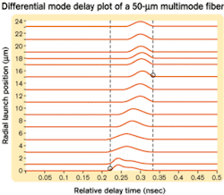
The results of a DMD measurement on a well-compensated (low DMD) fiber would look something like Figure 2. Note that in this example, circles and dotted lines mark the fastest leading edge and the slowest trailing edge in the DMD data set.
With the advent of a new 850-nm laser-optimized 50-µm fiber for the 10-GbE application, fiber manufacturers not only needed to measure DMD in a more consistent manner, but they were also required to measure it more accurately and with higher resolution to ensure 10-Gbit/sec performance. To achieve these goals, the TIA and IEC working groups drafted test procedures for DMD measurement (TIA FOTP-220 and IEC 60793-1-49), which established requirements for the most critical aspects of the DMD measurement: the characteristics of the pulsed "probe" laser and the positioning of the laser spot during measurement. The drafts state that the DMD probe laser should:
- Possess a narrow spectral width, or methods must be provided to compensate for a broader spectral width to minimize errors caused by source chromatic dispersion.
- Create Gaussian pulses with temporal widths that are <110% of the DMD to be measured.
- Launch a Gaussian spot with a mode field diameter of about 5 µm to limit the number of mode groups excited at each measurement position and maximize DMD resolution.
- Produce high-power pulses to maximize signal to noise, given that the typical attenuation of 50-µm fibers at 850 nm is approximately 2.5 dB/km.
These requirements effectively limit the choice of sources to Ti:Sapphire lasers and distributed feedback semiconductor lasers. More commonly available 850-nm Fabry-Perot lasers meet some requirements, but their spectral widths are too wide and 850-nm VCSELs, while spectrally narrow, typically produce only a few milliwatts of power, which would limit the measurement range of the system.
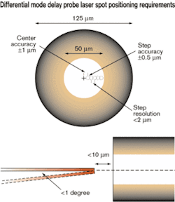
Once a suitable probe laser is identified, it must be possible to position the output spot of the laser in such a way that it is:
Each of these positioning requirements serves to ensure the accuracy and reproducibility of the probe-laser spot location and diameter as well as the angular orientation of the laser launch beam (see Figure 3). This prescription not only helps to ensure the "correct" mode groups are being excited at each measurement position, but it also improves the reproducibility of the DMD measurement.
Given these stringent test requirements, the question facing fiber manufacturers that want to produce "next-generation MMFs" for the promising 10-GbE market is: How can a measurement process, which was developed largely in a laboratory setting, be performed accurately and safely in a production environment? After all, precision movement of fibers using expensive fiber manipulators mounted on vibration isolation tables and using high-power Ti:Sapphire lasers and high-frequency detectors might be workable in a laboratory environment, but it is clearly a less than optimal solution for the production floor. In addition to the physical configuration of the test system, prospective 10-Gbit/sec MMF manufacturers also need to consider how DMD measurements can be performed efficiently in production, so the cost advantage of the 850-nm links that employ these fibers is not diminished by longer measurement times and higher fiber production costs.
The simple answer to this question is that DMD measurements, like other optical-fiber measurements currently being made in production, need to be performed using a test system that possesses most, if not all, the following attributes:
- Compliant. Performs measurements in compliance with applicable standards.
- Accurate. Produces results in agreement with current industry "reference testbenches" and offers traceable calibration for critical test parameters.
- Reliable. Built on a production-proven platform suitable for 24/7 operation with built-in performance assurance capabilities.
- Operator-friendly. Able to deliver operator-independent results when used by current production test staff.
- High-speed. Minimal fiber preparation, setup, and measurement times.
- Flexible. Compatible with the full production distribution.
- Adaptable. Can be modified to adapt to changes in measurement procedures and resultant computation methods.
- Multifunctional. Able to perform other key measurements on the same platform with one fiber preparation.
Given that DMD measurements are a relatively new "specifiable" fiber parameter and the market for DMD test systems is still relatively small, it is not surprising that commercial test systems that possess all the above attributes are rare. Manufacturers should seriously consider the commercial DMD measurement systems that have recently appeared on the market before embarking on the development of a home-built solution or deciding to deploy an existing laboratory setup in the factory. These new test systems can provide the measurement performance required and may possess many, if not all, the above attributes critical to successful production testing.
With measurement capability that meets their requirements, makers of next-generation multimode fibers will not only be able to guarantee their fibers will perform as designed, but also that they will be as cost-effective as the framers of the IEEE 10-GbE standard had originally hoped.
David Kritler is marketing manager at Photon Kinetics (Beaverton, OR). He can be reached at [email protected].


