By Ole Andersen
Overview
A variety of standards-compliant approaches to protection are now possible, enabled by hardware-based continuity check message generators and checkers. The right approach depends on the application.
Ethernet is the preferred technology for deploying metro area networks. However, without protection and redundancy, Ethernet networks will not meet the 99.999% availability requirement critical in many applications.
In legacy SONET/SDH networks, protection and redundancy are paramount. As a result, equipment vendors have implemented this as a natural part of basic functionality. Metro Ethernet networks based on SONET and SDH for the transport layer require protection and redundancy, in this case inherited from SONET and SDH and improved further by the Link Capacity Adjustment Scheme (LCAS) protocol. In native Ethernet-based metro networks, protection and redundancy are based on spanning tree and link aggregation control protocols. Both are proven protocols but with slow convergence time far from the sub-50-ms failover time required in many carrier applications.
The ITU, IETF, and IEEE have developed a range of Ethernet standards to improve maintainability and reliability in metro Ethernet networks, and the Metro Ethernet Forum (MEF) is likely to leverage these standards. These standards place additional requirements on Ethernet equipment, some of which can be handled by enhanced software protocols. However, to obtain the full benefit of these protection schemes, additional circuitry is needed.
Protection can be divided into network protection and equipment protection. Network protection has redundant links that protect against failures in the transmission path, which could be caused by broken cables, fiber or copper. Equipment protection is protection against failures in the actual transmission equipment–either failure on a single port or a complete node. Both protection types require redundant equipment and monitoring to detect failures in the network.
Fault detection: The Ethernet weakness
Monitoring and error detection can be a weakness in Ethernet compared to SONET and SDH. SONET and SDH have monitoring built in on the Regenerator, Multiplex, and Path section levels, with each level boasting a parity check (e.g., BIP-8) and trace identifiers. Ethernet has a cyclic redundancy check (CRC) on each transmitted frame. If no frames are transmitted, there is no way to fast-detect a failure on a link or detect failures on a path.
The first standard way to include link check is defined in IEEE 802.3ah, also called Ethernet in the first mile (EFM) or IP-less management. This standard, now incorporated in IEEE 802.3-2008, defines the operations, administration, and maintenance (OAM) sublayer, which provides mechanisms useful for monitoring link operation such as remote fault indication and remote loopback control. The link-based OAM information is conveyed in slow protocol frames. As these Link-OAM frames are sent each second, their handling requires little processing power, which makes them a powerful mechanism for monitoring network links and for fault location that is being heavily deployed into customer premises equipment (CPE).
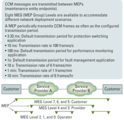
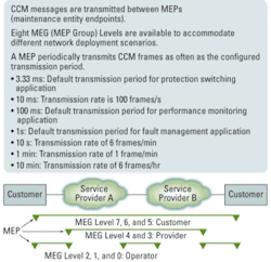
A more comprehensive standard for monitoring and error detection is the IEEE 802.1ag Connectivity Fault Management and the ITU version Y.1731/G. Included in these standards are the continuity check message OAM frames (OAM-CCM) that traverse a complete network path. OAM-CCM, also called Service OAM, is a way to detect loss of connectivity and to detect misconnections (see Fig. 1).
With transmission rates as fast as every 3.33 ms, substantial processing power is required. For a few ports a software-based approach may suffice, but such mechanisms do not scale well on Ethernet switches with dozens of ports. Similarly, the software-only approach does not scale to support switches capable of handling thousands of MEF-defined services. Special hardware such as a hardware-based CCM generator and checker are needed to support more than a few connections worth of CCM messaging.
Transmission of OAM-CCM frames is straightforward, as the same frame is continuously transmitted at the specified rate. The ingress is more complex because first the frame must be classified as an OAM frame and then the content must be checked for the correct level, MEG, and MEP ID period. If no CCM frames from a peer MEP are received within an interval equal to 3.5× the receiving MEP’s CCM transmission period, loss of continuity with the peer MEP is detected. It is important to send and receive CCM frames at highest priority to avoid erroneous failure detection in a congested network.
The hardware-based CCM generator and checker have been implemented in FPGAs, along with the development of the standards. However, this approach can be cost-prohibitive for volume deployment so Ethernet equipment vendors are now implementing it as an integral function in Ethernet switch chips.
Fast Ethernet protection switching
With service OAM in place, it is now feasible to implement protection switching in less than 50 ms, which is required in many carrier applications. Protection is normally implemented on either a port level or service level.
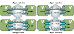
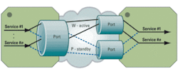
Figure 2 illustrates the port protection schemes supported by Carrier Ethernet switches. Unique copies of OAM and control-plane frames can be sent and received over each port independently. The hardware-based CCM features can be used in the selection of the active port and failover process.
In 1+1 port protection, traffic is sent over both ports by the transmitter and the receiver selects which port to use. Both ports are preprovisioned, enabling a fast failover by the receiver. The 1+1 port protection can be unidirectional or bidirectional, which requires an automatic protection switching (APS) protocol.
The 1:N port protection and the subset 1:1 port protection use active links and one standby link. Both ends must select the active ports, and in case of a failure, a switch to the standby link occurs. Always bidirectional, the 1:N port protection requires an APS protocol that is carried in OAM PDUs as defined in ITU-T Rec. Y.1731. Note that 1:N port protection is not defined in ITU-T Rec. Y.1731 but is easily implemented as N instances of 1:1. In this case, N instances of the APS protocol are running.
Link aggregation has been the traditional method for link redundancy that is advantageous to load sharing without a protecting link. All ports are active in the link aggregation group and traffic is distributed per flow between all ports. For all these protection types, the use of OAM-CCM allows protection switching times down to approximately 10 ms (3.5× the CCM rate).
Ethernet ring protection
In SONET and SDH networks, the ring topology has been widely used due to its ability to protect against both link and equipment failures. To leverage these advantages, ITU-T has developed a similar protection mechanism for Ethernet that is described in ITU-T Recommendation G.8032/Y.1344 Ethernet Ring Protection Switching.
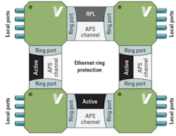
Each node in a ring protection network has two ring ports (east and west) and a number of local ports. As shown in Fig. 3, one link in the ring is designated as the ring protection link (RPL) and used only for redundancy. Each link reserves a VLAN to be used for OAM (APS channel). The APS OAM is used over each APS channel to assess the health of the link. G.8032/Y.1744 specifies protection switching performance of less than 50 ms in a ring with up to 16 nodes and 1,200 km of fiber. Again, this requires hardware-based CCM generator-checkers.
FIGURE 3. An overview of Ethernet ring protection.
E-line service protection
In service protection, each port may carry many services. The principles are the same as in port protection where two services such as E-Line Ethernet virtual connections (EVCs) are provisioned with one working and the other on standby (see Fig. 4).
One copy of each frame is sent, and the receiving end selects the active EVC. Unique copies of OAM and control frames are sent on each service independently for the selection of the active service and initiation of the failover. Typically, an Ethernet switch at the edge of the network needs to handle thousands of services and requires efficient service classification and special hardware functionality for fast protection switching.
With the introduction of PBB-TE, protection of a complete Ethernet switched path (ESP) comes into play and is more efficient and manageable in many networks versus individual services. ESP protection works in the same way as 1:1 and 1:N port protection; frames are forwarded on the active path and each path has independent OAM for fault detection. Both active ESP and protecting ESP are preprovisioned, having an individual backbone destination address (B-DA) and backbone VLAN ID (B-VID) with identical service IDs (I-SIDs) and service instance tags (I-TAGs). Load sharing is achieved with two active ESPs, each with the other as protecting. When a failover occurs, all services running on the two ESPs end up on the remaining ESP.
Beating 50 ms
In this article, different Ethernet protection schemes have been discussed and can be easily extended to more advanced schemes such as ring ladders and E-LAN and E-Tree services, to name a few. The standards are in place with ITU-T Recommendation G.8031/Y.1342 Ethernet Protection Switching and G.8032/Y.1344 Ring Protection Switching to ensure compatibility among different equipment vendors.
With connectivity and fault detection based on OAM-CCM messages, it is now possible to achieve switch times way below the 50 ms required in many telecom networks–especially in mobile backhaul networks. With standard Ethernet chips supporting hardware-based CCM, service awareness, and protection switching in hardware, the benefits of scalable carrier-class Ethernet networks can more easily be realized.
Ole Andersen is a senior applications engineer at Vitesse Semiconductor Corp.
Lightwave:OAM Separates Carrier Ethernet 2.0 Forest from the Trees
Lightwave Online:Infonetics: Carrier Ethernet Recession Proof
Lightwave:End-to-end Ethernet Testing Matures
