New test techniques required for CFP 100G optics
By PAUL BROOKS
As with every new technology, 100G is part evolution and part revolution, with the new CFP (C form-factor pluggable) optics a revolutionary step. Via new electronic, photonic, and software technology, the CFP offers the enabling step for cost-effective and successful 100G deployment. In particular, the 100G LR4 CFP module will economically address the challenge of aggregating traffic from routers to transport equipment at distances up to 10 km.
Most operators recognize the need to perform deep testing to ensure they make the right equipment choices and deliver maximum quality of service (QoS) to end users. During the testing process, it's important to identify signal integrity concerns such as noise, crosstalk, and impedance, and diagnose PCB and connector issues.
Major testing challenge
The IEEE 802.3ba standard, ratified in June 2010, details specifications for support of 40- and 100-Gbps Ethernet (40-GbE and 100-GbE) data rates, including 100GBase-LR4. Meanwhile, the CFP Multi-Source Agreement (MSA) defines a hot-pluggable optical transceiver form factor to enable 40- and 100-Gbps applications, including 40 GbE and 100 GbE. Client interfaces based on pluggable CFP optics are now appearing on routers, switches, and transport equipment.
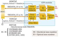
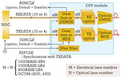
The integration of so many complex, high-speed photonics and electronics inside a CFP module presents major challenges both for network equipment manufacturers and operators. The gearbox in particular is a very challenging technology to get right (see Figure 1), and there are also multiple issues with both the photonic and electrical interfaces that play critical roles in interoperability.
Operators, who have on occasion seen early technology adopters struggle with novel photonics, want to make sure that the new CFPs work reliably without errors and interoperate with other standards-compliant modules. The fact that the first-generation CFP modules are expensive, above $30,000 in many cases, only heightens this desire. For these reasons, the CFP testing process must go deeper than simply unframed bit error rate testing (BERT), which has traditionally been used to validate optical modules.
The testing source should mimic real-world signals to verify the transparency of the gearbox and electrical/optical and optical/electrical interfaces. The use of parallel data lanes makes it essential to measure inter-lane skews (the difference in propagation delay among the different lanes). With four optical wavelengths, all of the current optical parameters such as power, stability, stressed eye sensitivity (SRS), and eye pattern have to be measured simultaneously to validate the time delay among signals and skew on the different wavelengths. With data carried over 20 virtual lanes, 10 electrical lanes, and four optical lanes, identifying the domain in which errors have originated is critical.
Basic testing
The first test should normally be a simple optical loopback with attenuation. The CFP is inserted into the tester and the tester is set up to run a simple traffic test - either unframed, PCS, Ethernet, or Optical Transport Network (OTN) as required. The optical output from the CFP is looped via an optical attenuator back to the receive (Rx) port of the CFP. The tester first validates the CFP with an MDIO computability check. The next step is running a traffic test and looking for errors.
An unframed pseudorandom bit sequence (PRBS) or digital word that can fully stress the electrical and optical layers provides the basis for first-pass testing for CFP transponders. Normally a 10x10-Gbps PRBS/digital word can be used to validate continuity, but a 10-Gbps per lane pattern is not transparent to a 10:4 gearbox. The mux/demux process can scramble the bit order, leading to an invalid pattern. So it is necessary to use a gearbox-transparent pattern generator that offers 20 logical lanes, each with a 5-Gbps PRBS or digital word bit-sequence muxed into 10 physical lanes.
It is important that test systems report both erroneous zeros and erroneous ones as well as the conventional error count. This capability can help determine error bias, which can be an indication of which circuit function is failing. Longer patterns and digital words can also be used to stress clock recovery and DC balance aspects of the circuitry. The test system also should allow for offsetting the PRBS patterns in time to remove any bit-wise correlation between lanes that could lead to crosstalk. The latest generation of test systems also provides an algorithm that can predetermine which 25-Gbps wavelength each 5-Gbps PCS virtual lane is mapped to, enabling the user to easily determine if errors are correlated with a 10-Gbps lane (electrical issue) or a 25-Gbps wavelength (photonic issue).
An optical eye test is performed by connecting a high-bandwidth scope with a suitable optical/electrical interface to the test system. An eye diagram is commonly used to review the transmitter waveform and evaluate transmitter performance. The data patterns are superimposed upon each other using a common time axis, typically a little under two bit periods in width.
The CFP transmitter should avoid gray areas in the center of the diagram that are midway between logic 0 and logic 1. Masks are often placed in the center of the eye in areas where the waveform should not exist to aid in verifying that the eye is open. To perform this test with accuracy, it is important that the test equipment driving the transponder has high bandwidth and a low jitter trigger.
Static and dynamic skew
At 10 Gbps per lane, only 100 psec exist per unit interval (UI), so even a small change in timing per lane may represent a significant part of the whole UI. The latest test systems enable control of two types of skew variation. The first controls variation on the whole UI on a per-lane basis, which is the standard static skew approach. This provides a useful indication at the PCS layer of the performance of the per-lane first-in/first-out (FIFO) buffer depth.
The second measurement, dynamic skew variation, is established as a mandatory test by IEEE 803.3ba. Dynamic skew variation ensures that the individual lanes continue to track correctly despite skew changes across a range of ±2 UI. Maintaining the dynamic skew tolerance ensures that any propagation delay variation in individual 10-Gbps output buffers will not cause bit errors in the line receivers.
The MDIO serial control also requires performance validation over a wide range of operating conditions. A debug application can ensure that the MDIO correctly identifies parameters such as optical power, temperature, voltage, and vendor ID. The user can exercise peek/pole, block read, etc., and check the operation of control pins.
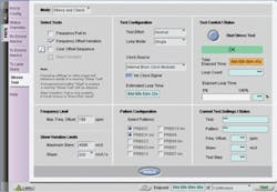
Stress testing parameters such as dynamic skew and clocking pulling range can be used to provide complete confidence in module performance (see Figure 2). The user can select options for skew, clock offset, PRBS, etc., or pick a fully automatic canned transponder validation test. Impairments in the optical lane can be augmented by electrical lane skew to fully test the margins of the electro-optics. Monitoring the performance of the receiver makes it possible to see the precise point at which the line card starts to produce errors. PCS layer alarms and errors can be fully validated against standards.
CFPs are the key to cost-effective and reliable 100G deployment, and so they require extensive testing and characterization. The testing challenges posed by 100G are formidable but the latest generation of test and measurement equipment is up to the challenge. New testers deliver complete coverage from the physical layer through the photonics layer while analyzing PCS/Ethernet traffic and providing deep OTN analysis with dynamic skew.
Breadth and depth of test coverage for CFPs coupled with applications that quickly highlight and diagnose issues is the key to quick and effective deployments.
PAUL BROOKS is product manager for Communications Test and Measurement at JDSU.


