By OLIVER FUNKE
Are measurements for complex modulated signals ready for standardization?
The success and broad acceptance of complex modulation in optical transmission, especially in core networks, and the development of a new test instrument, the optical modulation analyzer, to measure signals that use these formats, raise questions about what are the best parameters to determine the quality of complex modulated signals and whether test conditions should be standardized.
Before a new test parameter or method is broadly accepted, existing methods must be proven to have severe limitations, if they work at all. The next step is a standardization process for a new method or parameter and its test conditions. In some cases where a new quality parameter gives clear advantages in ease of use and cost of test, standardization will follow what is already broadly accepted and implemented.
We’ll analyze whether the industry needs a new parameter to quantify complex modulated signal quality and consider the necessary steps to make such a parameter broadly accepted and standardized.
Do we need a new quality parameter?
In conventional on/off keying (OOK), we use only one dimension to code the information onto the carrier signal, represented by the amplitude of the light. In complex modulation, we typically add one more dimension besides the amplitude – the optical phase. The quadrature phase-shift keying (QPSK) modulation scheme is a special case where information is coded only in the phase of the carrier signal, but the signal is still usefully represented in two dimensions. (Since dual polarization is more like an additional transmission channel than a third modulation parameter, we do not need to consider that as a third dimension.) This two-dimensional coding already implies an answer to the question, Do we need a new quality parameter for complex modulated signals?
Before analyzing this element in more detail, let’s look at how OOK signals are typically specified and analyzed and the obstacles to transferring this concept to complex modulated signals.
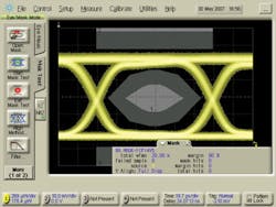
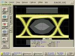
Figure 1 shows typical parameters derived from an eye diagram of on/off keyed signals. In many cases an estimate of the bit-error ratio (BER) is derived from the noise distribution during the ‘1’ and ‘0’ amplitude segments of the signal. Assuming a Gaussian noise distribution, the Q-factor can be derived, which is then directly related to the expected BER, based on statistical rules.
In addition, a hit ratio of the mask is often determined as another parameter describing the quality of the signal or system. Performance standards specify a limited number of allowed hits of the mask. This mask is defined in a standard, and the relevant influencing factors from measurement receiver behavior are standardized, e.g., the use of a Bessel-Thomson filter with defined bandwidth at the input of the test instrument.
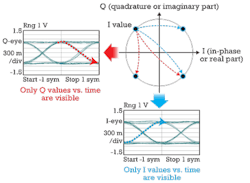
Looking into the details of what an eye diagram presents when applied to a complex modulated signal, we immediately see problems. We’ll start with a QPSK signal as used on current 100-Gbps transmission systems. Figure 2 illustrates an eye diagram of a QPSK signal. The eye diagram is a projection of the signal to the real or quadrature axis, resulting in a set of two eye diagrams for complex modulated signals.
We can see, for example, that a transition from low to high in the I-graph does not let us distinguish whether this transition is from a ‘01’ symbol to a ‘11’ symbol or ‘10’ symbol as shown in the constellation diagram. For the Q eye, we of course have the same ambiguity, leaving doubts about the helpfulness of eye diagrams in characterizing complex modulated signals.
In OOK, the best decision level is usually determined by changing the decision level in small steps and calculating the Q factor or BER at each step. The lowest BER occurs at the optimum decision level. Since a coherent receiver doesn’t decide based on an amplitude threshold, but instead on a two-dimensional search for the nearest symbol in the constellation diagram at a distinct time, the role of the eye diagram in measuring signal quality is also less direct.
An additional complication – the need to distinguish between the eye diagrams of the I and Q projections – requires a clear documentation of the assignment in test.
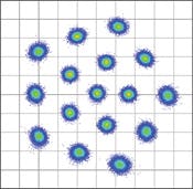
Finally, consider the example of Figure 3, which shows the result of a special 16-QAM (quadrature amplitude modulation) constellation.1 This QAM signal features nonrectangular distribution of the constellation points, which improves robustness against distortions along an optical link. Looking at the projected axes of this signal makes it immediately clear that any signal quality measure based on eye-diagram analysis would fail.
In summary, we cannot just keep the test concepts we used in OOK without severe limitations due to:
- Additional modulation dimension of a complex signal compared to OOK.
- Ambiguity of eye diagrams with respect to projections of the I and Q axis.
- The prospect of higher-level QAM signals that make the relationship between results and the eye-measurement parameters nearly intractable.
Since QPSK is a special case with only one modulation parameter, there are several measurement approaches on the market that apply test concepts from OOK to complex modulation. This might work well for the time being, but the limitations we’ve described are on the horizon.
What are the alternatives?
Fortunately, the optical communication industry can learn from the RF mobile communications industry, which addressed this issue more than a decade ago when switching from pure AM and FM modulation to complex modulation to realize higher data rates with digital transmission. The RF industry developed the concept of error vector magnitude (EVM), which is common in standards like WLAN. It is based on a very simple idea: “What is the deviation of my received signal from the ideal signal?” That’s what EVM measures. The reason this concept is broadly adopted in the RF world is that it overcomes the limitations described earlier.
We can compare the measured signal against an ideal signal at any number of amplitude and phase levels and against any positions of constellation points we define. This approach leaves no ambiguity, since each measured constellation point is related to its nearest ideal neighbor. A false association implies a symbol error in the same manner as it would occur in a real transmission receiver.
This concept implies also that the measurement receiver is only needed to measure the signal at the same time point that a real receiver would use to decide what kind of symbol was received. Any information about the transition is not of interest in this concept. Of course it can be extended to also measure during the transition, but this would be most helpful if the result is compared to a standardized transition.
Another important point is that the EVM calculated as a root mean square value over a statistically significant number of vectors can be used to calculate a Q factor. Therefore, EVM has a direct relation to the BER under the same conditions as with OOK, namely a Gaussian noise distribution.2
Major EVM dependencies
As described earlier, the major test condition requirement for OOK is the Bessel-Thomson characteristic for a reference receiver. For complex transmission receivers, we have other influencing parameters like:
- Receiver bandwidth.
- Receiver transfer characteristic.
- Receiver impairments like skew.
- Noise.
- Effective number of bits of the analog-to-digital converter (ADC).
- Receiver distortions.
- Signal processing algorithm.
One of the most discussed parameters is the electrical bandwidth over the path between the PIN diodes and the ADC, including of course the ADC itself.
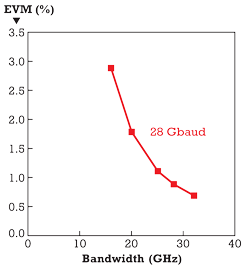
Figure 4 shows, based on a simulation, how electrical bandwidth can influence an EVM measurement result. It is shown that, for bandwidths between 22 and 25 GHz, the EVM is influenced in the order of 1% for a 28-Gbaud QPSK signal.
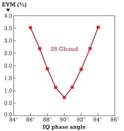
Of course, it is not sufficient to evaluate the influence of only one parameter. Phase error introduced by manufacturing imperfections within the optical hybrid of a coherent intradyne receiver is an example of how optical components can degrade receiver performance. Figure 5 illustrates the simulation of the error in phase angle of an optical IQ hybrid.
In version 1.1 of the OIF Implementation Agreement for integrated coherent intradyne receivers, a phase angle error of ±5° is allowed for the optical hybrid, which would introduce an EVM error of about 3%, according to the simulation.
Finally, even the way the signal processing, especially phase tracking, is implemented within a coherent optical receiver can lead to differences in EVM measurement results on the order of several percent or more in the case of signals with high phase noise caused by the transmitter laser.
The above examples indicate that using EVM as a generally accepted quality parameter might need more standardization effort than in the past.
Quality parameters for complex modulated optical signals need either a reference signal that standard institutes can provide as traceable artifacts or standardization bodies need to provide defined parameters for a reference receiver, including the impairment correction rules and signal processing framework. This signal processing framework does not need to be the same as is used in standard telecom receivers, so suppliers of telecom equipment would still be free to implement their own signal processing. In addition, they would benefit from test results that are comparable among various test instruments.
Status of the EVM standardization
The concept of EVM is well known in the optical community. However, it’s not really used as “the standard” for complex modulated signal quality and even less for BER estimation.
One reason might be that without defined measurement conditions for EVM, like in the mask test of OOK with a Bessel-Thomson filter, test results cannot be compared easily among different test instruments or telecom receivers using built-in EVM evaluation. Addressing this situation, the IEC subcommittee SC86C, “Fiber Optic Systems and Active Devices,” has initiated work on this topic. The subcommittee has prepared and is circulating a document that, when published, will provide a definition for EVM adapted to the optical communications industry and a framework for standardizing its measurement and the necessary conditions. ITU-T Study Group 15 has also taken up work on this topic to qualify telecom transmitters.
Until we have agreement on a definition or a standard for a reference receiver for EVM measurement, we will suffer from limitations due to different measurement conditions. The work done so far therefore needs to continue. Otherwise, economic penalties will result when the test results that module and component vendors derive aren’t comparable with those of system suppliers or service providers.
References
- Timo Pfau, Xiang Liu, S. Chandrasekhar, “Optimization of 16-ary Quadrature Amplitude Modulation Constellations for Phase Noise Impaired Channels,” ECOC Technical Digest 2011.
- Rene Schmogrow, et al., “Error Vector Magnitude as a Performance Measure for Advanced Modulation Formats,” IEEE Photonics Technology Letters, Vol. 24, No. 1, Jan. 1, 2012.
OLIVER FUNKE is product manager in the Digital Test Division of the Electronic Measurements Group at Agilent Technologies.
