By Joe Evangelista
Until recently, PON device tests were limited to short fiber cables. New technology enables device test with longer cable runs.
Test engineers are interested in understanding the effects of long fiber lengths on the quality of the original transmitted signal from a PON’s optical network unit (ONU). A test engineer, for example, can characterize the optical power attenuation through a network by monitoring bit-error counters on a bit-error ratio tester’s (BERT’s) error detector. The BERT’s error detector could monitor BER in real time as optical power is attenuated until errors are encountered, providing information on the system’s optical sensitivity.
However, until recently, you could test PON devices in this way only with a short fiber cable, because the propagation delay between the transmitted optical signal and the received optical signal needed to be small. This article discusses issues related to measuring bit-error ratio (BER) when you test PON components at 1.25 GHz at the physical layer with multiple kilometers of optical fiber inserted between the ONU transceiver and the optical line terminal (OLT) transceiver.
Fiber length matters
In past PON testing scenarios, a small propagation delay was necessary to ensure a synchronous clock with the transmitted signal could be used by the receiver to sample the incoming data correctly. The short propagation delay maintained phase coherency between the transmitted data and the associated synchronous clock provided by the transmitter system. The receiver system used to sample the incoming data for bit error calculation requires a clock to properly align the received data with the expected data stored in the receiver system’s memory. Figure 1 illustrates a phase-synchronous clock able to sample incoming burst data received by a BERT’s error detector.
When you insert an optical fiber longer than several meters between the transmitted signal of the ONU and the receiving OLT, the BERT’s error detector can no longer use the BERT’s pattern generator clock to sample the incoming data to the BERT’s error detector. You might consider simply inserting another spool of optical fiber, the same length as the one used for transmitted data, between the transmitter’s synchronous clock and the clock input to the receiver system. Unfortunately, no two lengths of fiber behave in the same manner, so phase coherency cannot be assured between the clock used to sample the incoming data and the incoming data itself.
You then might consider using a clock data recovery (CDR) mechanism to re-establish a phase-coherent clock from the incoming data that could be used by the receiver system’s sampling hardware. However, PON systems use asynchronous time multiplexing, where an ONU sends data in bursts — not continuously — so network bandwidth can be used more efficiently by multiple ONUs on the network. Figure 2 illustrates a scope capture of burst data.
A traditional CDR requires a continuous data stream to ensure the output of a constant phase-coherent clock. PON systems development therefore required the development of a new type of CDR that could provide a constant phase-coherent clock when data is not continuous. The advent of the burst-mode data CDR (BCDR) fulfilled this requirement.
It also helped to solve the problem of testing PON devices with longer cable lengths. You can now use the BCDR together with a BERT that provides two synchronous differential pattern generators and a differential error detector. This type of testing is far more valuable because you can characterize devices under real-world conditions. Using a multichannel synchronous BERT along with a BCDR, you can gather greater insight into the optical performance of your PON devices under a variety of test conditions.
BERT requirements
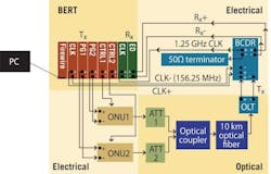
What is required from a BERT to ensure accurate BER measurements over multiple kilometers of optical fiber on a PON system? The BERT’s pattern generator needs to provide voltage-adjustable differential electrical data outputs connected to the electrical inputs of a transceiver used as an ONU on the network. The optical transceiver used as the OLT will have its electrical output sent to the BCDR, where the data and the 1.25-GHz clock will be realigned and sent to the BERT’s error detector clock module along with the synchronous differential data to the error detector. This enables BER testing on the data signal containing all the dispersive effects created by the long optical fiber.
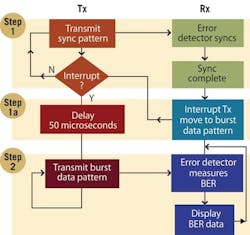
Figure 4. Data flow between the transmitter of the BERT and the error detector of the BERT in a test scenario using 10 km of optical fiber.
Before we implement a long optical fiber, we need to ensure the ability of the BERT to work with the BCDR in a back-to-back mode between the TX and RX. This test verifies the ability of the BCDR to maintain a constant clock to the BERT’s error detector clock module in the presence of long gap times where no data transitions were provided to the BCDR.
You also need a BERT that can perform a gated BER measurement. In this mode, the BERT’s error detector can be configured to measure only BER during the payload portion of the burst and ignore the bits in the preamble and guard time.
The BERT should also be able to provide the various synchronous control signals, such as Laser Enable and BCDR Reset, that need to be in tight time coherence with the particular data burst. The BERT’s pattern generator should provide a 156.25-MHz clock to the BCDR along with the differential data. The BERT’s error detector clock module is then driven with the recovered clock from the BCDR along with the differential data coming from the BCDR. Once you start the BERT’s pattern generator and error detector, you should see error-free operation. The BCDR used in this experiment is controlled through an I2C bus.
PON device test examples
You could experiment with using the BCDR and a BERT error detector along with multiple kilometers of fiber as illustrated in Figure 3. In this experiment, additional delays will be handled that were not present when using the BCDR with only hundreds of nanoseconds of propagation delay between the transmitted optical signal and the received optical signal. The data being sent through the optical fiber no longer is in phase with the original BERT pattern generator clock, but the BCDR handles that issue. The BCDR maintains a clock that is in phase with the realigned data being sent to the BERT’s error detector.
Combined with the BCDR, a BERT that provides the ability to synchronize with a simple continuous pattern and then coherently switch to the burst-mode test pattern without loss of timing synchronization between the transmitted data and the expected data provides important flexibility for characterizing the physical-layer operation of the network. Figure 4 illustrates the data flow between the transmitter of the BERT and the error detector of the BERT during this process.
In another example experiment, 10 km of optical fiber is placed between the ONU and OLT. You need to calculate the propagation time of the data through the optical fiber at 1.25 Gbps. A BERT needs to be able to handle the long propagation time of the data through the fiber.
One way to remove the propagation delay through the fiber is to create a data pattern that completely fills the optical fiber in one repetition. To calculate how much data is required to fill the optical fiber, you need to know the speed of light, the length of the optical fiber, and the bit period of the data signal. The speed of light through fiber is 2x10⁸ m/s. The experiment uses 10 km of optical fiber or 1x10⁴ m.
The following equation calculates the time it takes for light to travel through 10 km of optical fiber.
Optical fiber length in meters (l) ÷ Speed of light in meters = Travel time of light in seconds (t)
We know our optical fiber has a propagation time of 50 µs; once we know the bit period, we can calculate how many bits it will take to fill the fiber. The following equation calculates the number of bits it takes to fill the fiber with 50 µs of propagation time when the data signal’s bit period is 0.8x10⁻⁹ seconds or alternatively a data rate of 1.25 GHz:
Travel time of light in secs ÷ Data signal bit period (B) = Number of bits to fill optical fiber
In this example, the BERT will use a data pattern for synchronization that is at least 60 kbits in length. It is important to fully fill the fiber because the data stream used to perform BER testing is not the same as the BERT’s data synchronization pattern.
Ensuring the fiber is filled with one complete repetition of the synchronization pattern will guarantee that once the BERT’s pattern generator and error detector move from the synchronization process to the BER measurement process, there is no portion of the synchronization pattern in the optical fiber. If there were, we would measure some number of errors on the error detector until the fiber is completely empty of the synchronization pattern data. Once the Rx moves from step 1 to 1a in Figure 4, both the Tx and Rx are in absolute time correlation, and the delay of 50 µs imposed on the Tx will ensure the error detector will be measuring the burst data pattern once both the Tx and Rx arrive at step 2.
Flexibility is the key
A BERT that provides flexible control of an ONU’s data burst contents and length along with user-definable data for its preamble enables you to characterize a wide variety of device behavior. A BERT also needs to be able to provide a number of low-speed control signals that are time coherent to the burst data.
The BERT’s analyzer system needs to support a gated BER measurement where the BERT can be configured to indicate which bits of the ONU data burst should be included in the BER measurement and which should be ignored. A BERT used for PON testing should also be scalable for testing 1.25-Gbps and 10-Gbps PONs.
Joe Evangelista is a high speed digital and analog application engineer at Agilent Technologies, Inc.


