By Stephen Hardy
Interest in low-latency networking has exploded, thanks in large part to the rise of algorithmic trading in the financial community. But what causes latency, and how can you avoid it?
There’s nothing latent about the current interest in low-latency networking. With algorithmic trading on the rise, brokerages and other financial institutions have demanded communications pipelines that enable them to execute their trade instructions as quickly as possible—and preferably more quickly than the competition. Carriers, particularly within the competitive access niche, have responded by examining their networks in hopes of removing any element that might slow a signal on its journey from the brokerage desk to the trading floor.
Certainly applying optical communications technology is a logical first step, since nothing beats the speed of light, right? But there’s more to removing latency than lighting fiber, particularly when customers base their communications service decisions on latency differences in the microseconds. Scrubbing latency from the network requires careful infrastructure planning, as well as a variety of tradeoffs.
The elements of latency
Latency—the amount of delay a signal experiences in reaching its destination—has importance in a variety of communications applications, including military/government, research and education, disaster recovery, and high-end online gaming. However, the rise of algorithmic trading, which depends on precise timing and an accurate assessment of the current trading environment, has made low-latency connections essential within the financial community.
“I’m told today that the difference between winning and losing a trade is 250 ns,” says Jim Theodoras, director of technical marketing at ADVA Optical Networking, whose company has sold latency-optimized transmission equipment for several years.
Optimum LightPath is a competitive communications provider with a metro New York footprint, ground zero for the financial community. Says John Macario, senior vice president of product strategy and management at Optimum Lightpath, “Latency is table stakes in this game. If you don’t have a competitive latency number, the chances that you win that business are pretty slim. If you’re milliseconds different, you might as well forget about it.”
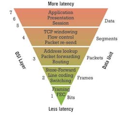
Latency can be introduced at each layer of the OSI protocol stack. Therefore, keeping the transmission at Layer 1 for as much as possible helps to lower latency. Source: ADVA Optical Networking
With the margin of error so small, carriers who hope to have financial firms as clients must examine every aspect of their networks. “For the longest time, people were ignoring the transport piece of it because it was kind of like, well, it’s light in the fiber, and how can I get faster than that? And they concentrated on the software layers, and they concentrated on the routers and avoiding congestion,” Theodoras explains. “But it quickly became evident to them that while they’re saving nanoseconds or microseconds at most in their switches, they can save milliseconds through a better transport strategy.”
That strategy often involves four primary elements:
- the fiber,
- the network elements,
- the line rate,
- the distance that needs to be traveled.
As carriers consider each of these, the interrelationships among them become clear—as does the fact that removing a latency-inducing element in one part of the network may force you to add one somewhere else.
The fiber foundation
“By far the biggest contributor to latency is the fiber plant,” says Jim Benson, head of DWDM sales, North America, Nokia Siemens Networks. While fiber age and type can have an effect on reach (which in turn could affect latency contributors within the network elements, as we will see), generally the inherent difference in latency between, say, large-effective-area fiber and standard singlemode isn’t huge, he asserts.
Yet, while the difference between fibers may not be large, their contributions to latency remain significant. According to MRV Communications, the refractive properties of fiber add about 5 µs of delay per kilometer.
Therefore, the shorter the fiber run, the lower the latency. For this reason, ADVA Optical Networking frequently partners with dark fiber providers and co-location facilities when it approaches potential financial customers, Theodoras says. The goal is to find the network onramps and off-ramps closest to the customer and where the signals need to go, plus the shortest connections among these elements.
Yet carriers can undo much of this planning if they then add 20 km or more of dispersion compensating fiber (DCF) to their network elements to support higher-rate signals or to offset poor-quality plant. For this reason, systems houses have integrated other forms of optical dispersion compensation into their equipment—which is just one area in which the design of network elements also can affect overall latency.
Latency is elemental
According to Per Hansen, senior director, enterprise networking, at Ciena, DCF could add as much as 15% to 20% to the average route, depending upon how often it needs to be used. For this reason, Ciena, like most other systems vendors, has incorporated compensation techniques based on fiber Bragg gratings to help keep the amount of fiber a signal must traverse to an absolute minimum.
Meanwhile, the other major low-latency thrust among equipment developers focuses on keeping the signal in the optical domain once it hits the fiber and on minimizing the amount of electrical processing at either end of the connection. Ideally, the trade command should run down the OSI protocol stack at the start of the transmission and not leave Layer 1 until it reaches its destination; it should also avoid optical to electrical to optical (OEO) conversions along the way.
The goal of minimizing electronic processing starts in the transponder, where most companies either employ a proprietary form of forward error correction (FEC) or, better yet, avoid its use completely. Hansen reports that card designers also can reduce the amount of distributed processing required, as well as perform some functions via signal taps as opposed to using the entire signal stream.
Once the signal hits the network, the less often a signal requires full 3R regeneration, the less latency it encounters. (Of course, no FEC means it’s more likely you’ll need regeneration, which is one of the tradeoffs we’ll discuss later.) Shorter routes are less likely to require regeneration anyway, but Nokia Siemens Networks has engineered its ultra-long-haul systems to obviate the need for regeneration as well, Benson says.
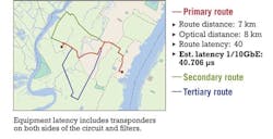
The effects of path length on latency are significant. As the routes increase in length, the amount of latency increases. Source: ADVA Optical Networking
Even optical amplification can add somewhat to latency, Theodoras asserts. ADVA Optical Networking builds its own single-stage EDFAs for this reason, which it sometimes pairs with Raman techniques. Other sources to whom Lightwave spoke feel that as long as an EDFA doesn’t contain DCF, its contribution to latency is negligible.
Overall, minimizing the number of network elements through which a signal must pass brings latency benefits. For this reason, particularly in updating legacy ring architectures built with back-to-back multiservice provisioning platforms or SONET/SDH switches, Bill Kautz, staff portfolio planning manager at Tellabs, recommends the use of packet optical transport platforms. “To the extent that you can integrate SONET and SDH switching or OTN switching or Ethernet switching within that element that includes the DWDM optics and ROADM, we feel that minimizes latency because you’re minimizing not just the OEO conversions, but the tandem ties and the processing between multiple systems,” he explains.
Line rate and distance
There’s nothing inherently faster about a 10-Gbps link versus a 1-Gbps link; light travels at the same speed regardless of the amount of data it carries. However, the intertwined elements of data rate and the link distance can influence which latency elements a carrier can avoid.
For example, a 10-Gbps connection will more likely need some sort of dispersion compensation. If it’s traveling a long distance, it also may need a boost along the way to be decipherable at the other end of the connection, whether that boost comes from FEC, regeneration, or some other source.
And at line rates greater than 10 Gbps, the question of coherent detection arises. Both the Tellabs and Nokia Siemens Network sources touted coherent detection as a boon to low-latency networking at 40 Gbps because of its ability to do away with in-line compensation elements. However, ADVA’s Theodoras, whose company has not embraced coherent detection as tightly as most of its competitors, views the intense electronic signal process coherent detection requires as a latency nightmare.
“Coherent detection by itself is horrendously high latency,” Theodoras says. “We’re talking milliseconds, and obviously you can’t have that unless you’re saving milliseconds somewhere else.”
Tellabs asserts its coherent detection approach includes a “bulk chromatic dispersion compensator” that adds only “several nanoseconds of delay.” Theodoras, meanwhile, allowed that if the link was long and the benefits of coherent detection enabled the removal or bypass of a sufficient number of network elements, the tradeoffs might make coherent detection’s latency acceptable.
Finally, data rate can have a latency effect when it comes to matching the size of the data stream to the pipe through which it will travel. Many transactions require 1 Gbps or less; however, many financial firms have leased 10 Gbps of bandwidth to ensure their trade doesn’t get choked in a sudden bandwidth surge. Loading a 1-Gbps signal onto a 10-Gbps pipe requires some sort of aggregation, a process that also can add latency. For this reason, Infinera has announced a “native waves” technology as part of its low-latency portfolio that enables priority 1-Gbps traffic to bypass aggregation functions and hop directly onto a 10-Gbps pipeline.
But whether the signal is 1 Gbps or 10 Gbps, the distance it must travel represents an important element of latency planning—not just for the inherent latency of fiber but for the secondary effects distance can create. These secondary influences can have a significant effect, for example, on the popular route between the New York and Chicago financial exchanges, a considerable distance regardless of how straight a fiber line a carrier might draw between the two points. As mentioned previously, ideally a carrier would like to avoid using FEC and full 3R regeneration. But how far can a signal travel without them? The answer to this question probably changes depending upon the data rate involved, whether dispersion compensation is required, and how many nodes the signal must pass through along the way.
Latency tradeoffs
For reasons such as these, few networks can attain the low-latency nirvana of the most direct fiber route; no FEC; no 3R regeneration; no grooming, aggregation, or multiplexing; and a line rate of 10 Gbps or greater. Therefore, establishing the lowest latency possible for a particular application usually involves tradeoffs among latency-inducing elements.
The one between the use of FEC and regeneration on longer links tends to be the most common; in many applications, the use of one or the other is required. To complete their low-latency tool kits, most vendors have developed proprietary FEC algorithms and/or encapsulation methods, as well as ways to get away with 2R regeneration—which usually involves re-amplification and reshaping, but not retiming—to avoid the use of FEC. In this latter category, ADVA will occasionally use what Theodoras called “2.5R,” which adds clock and data recovery to reshaping. Meanwhile, Infinera has touted an “ultra-low-latency” regeneration capability for its offering.
Tradeoffs also become more likely if the route in question is already in place. Fiber pathways may be set in stone (or concrete), nodes can’t be changed, and the carrier may be reluctant to rip out equipment that’s doing a perfectly fine job of carrying other traffic for which latency doesn’t matter.
But the opportunity to service customers with deep pockets may overcome the reluctance to re-engineer the network. Theodoras described the current spate of low-latency network engineering as a gold rush. “Sooner or later, everyone will reach parity,” he muses. “But until people do, it’s a big deal.”


