By Adel Asseh, PhD
Overview
Combining the power of fiber Bragg gratings with the simplicity of an ordinary patch cord results in a space-saving, cost-effective approach to dispersion compensation.
There are two known methods of performing dispersion compensation: fiber Bragg grating (FBG) technology and dispersion-compensating fiber (DCF). The newer FBG technology offers cost savings, lower insertion loss, and lower latency than the older, traditionally used DCF.
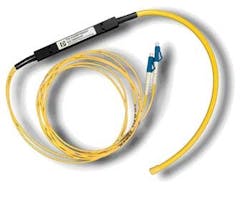
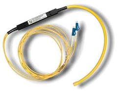
The latest innovation to leverage FBGs integrates the dispersion compensation module (DCM) into a patch cord (see photo). This design eliminates the need for a separate piece of hardware for dispersion compensation.
The dispersion compensation patch cord (DCM-PC) combines the dispersion-compensating power of continuously chirped FBGs with the simplicity of an ordinary patch cord. The rugged and cost-effective dispersion approach results in easy system in-design, effective system commissioning, and valuable system space savings.
A fiber-Bragg-grating-based dispersion compensation module is integrated into a patch cord, which eliminates the need for a separate piece of hardware to compensate dispersion.
Value proposition
The DCM-PC is aimed toward system vendors or operators that seek a simple and cost-effective approach to dispersion compensation. It addresses a broad application space, ranging from basic TDM systems to DWDM-based metropolitan and regional networks to channel or sub-band specific residual dispersion compensation in submarine DWDM terminals. Use of the DCM-PC can result in a valuable gain of system reach.
Traditionally, system vendors have used DCF spools to compensate single-channel systems as needed. In addition to the higher loss, DCF spools are very bulky.
Alternatively, designers can use DCMs, which can be based on multiple technologies. Yet even if these modules are significantly smaller than fiber spools, they are difficult to integrate into a transceiver board. For this reason, an extra board very often has to be used, which consumes valuable system space.
Instead of having dedicated and costly terminal space allocated for spools of DCF or DCMs, the DCM-PC can simply provide the same functionality while connecting one board to another—and simultaneously remove the need for two additional patch cords.
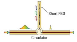
FBG-based dispersion compensation principle.
The ruggedness, unique form factor, and temperature insensitivity of the DCM-PC also make it possible to place it directly on the fiber tray. This benefit makes dispersion compensation an integral part of the fiber routing. An alternative placement is in the cabinet, beside the system.
The DCM-PC works particularly well for channel-specific dispersion compensation, i.e., channelized devices having set dispersion for a specific channel or channel plan, especially for SONET/SDH applications. Low loss is important in these applications. Low loss means less, typically channel-specific amplification, which further addresses cost and space requirements. Moreover, this low loss means that the transceiver reach can be extended.
The DCM-PC also has virtually no latency, which is a huge advantage over DCF for time-critical applications such as gaming or banking.
The DCM-PC can also be used to “unbias” the dispersion map of 10-Gbps transceivers when mixing 10- and 40-Gbps signals in the same system. Often, 10-Gbps transceivers are biased with a large designed residual dispersion and a “working point” off the nominal (zero) dispersion. On the other hand, 40-Gbps transceivers have a much narrower dispersion window that usually needs to be centered around the nominal dispersion.
The DCM-PC enables designers to modify the dispersion map on a per-channel basis to accomplish this unbiasing. They can reduce the dispersion to around zero and combine the 10- and 40-Gbps transceivers more easily.
Design
A DCM-PC consists of a circulator in which the second port is spliced to an FBG fiber (see Figure). The required grating length is governed by the dispersion and optical bandwidth. The product of the bandwidth multiplied by dispersion should be less than 6,500 ps so the gratings won’t be too long. A short grating length gives several advantages, including ultralow loss, no latency, and no nonlinear effects.
The other two ports are connectorized, which means that the DCM-PC replaces two ordinary patch cords in most cases. All common connectors are supported.
Latency is an increasingly important parameter to consider. In time-critical applications such as financial transactions where automated market making and high-frequency trading are done, every microsecond saved is crucial.
Performance
System vendors today use a variety of transceivers. Beside the fixed designs there are several pluggables like SFP, XFP, XENPAK, etc. The transceivers for 10 Gbps (and 10.7 and 11.1 Gbps) using avalanche photodiode receivers typically have a receiver sensitivity of –24 dBm (error-free using standard forward error correction). A typical specification for the minimum output power is 0 dBm EOL.
To calculate the available link budget we must consider the dispersion penalty at the maximum allowed dispersion. A typical value is 2 dB at 1,600 ps/nm, which corresponds to about 90 km of standard singlemode fiber. Furthermore, transmission fiber is quite good nowadays. So we can assume a fiber loss of 0.22 dB/km.
Using these assumptions we will get a maximum distance of 90 km limited by the maximum allowed dispersion.
With the addition of a DCM-PC in line to provide compensation for, let’s say, 60 km, we can disregard the dispersion penalty since we will be well below the dispersion limit for the transceiver. However, we must deduct the insertion loss of the DCM-PC, leading to a loss-limited distance of 109 km.
The extra 19 km is vital in many applications. Note that you can’t achieve the same effect using traditional DCFs due to their higher insertion losses.
Some vendors have better-specified transceivers. An example with Rsen=–27 dBm, Pout min=3 dBm, and 3-dB power penalty at 1,600 ps/nm leads to the following comparison: 90 km without and 136 km with a DCM-PC. In other words, use of the DCM-PC enables another 46 km.
To summarize, a DCM-PC can extend the reach in single-channel applications considerably while offering a more flexible system layout and lower cost. The DCM-PC is also very useful in systems with mixed 10- and 40-Gbps transceivers to unbias the 10-Gbps dispersion map.
Adel Asseh, PhD,is a founder of Proximion and director of technical sales.
Links to more information
LIGHTWAVE: FBG Dispersion Compensation Improves Amplification Designs and Strategies
LIGHTWAVE: Industry Plots PMD Compensation Paths at 40G, 100G


