Architecture Choices in FTTH Networks
More than a decade has passed since the first fiber to the home (FTTH) network deployments, starting with Japan and Italy. Yet the cost of building a network remains the primary obstacle to ubiquitous fiber connectivity for every household. According to news reports, from 2005 to 2015, the cost per home passed dropped from $1,021 to just under $700. Why does Moore's Law apply to transistor density and disk storage capacity, but not to FTTH?
The labor factor in FTTH costs
Building an outside plant fiber network can be labor-intensive. Construction, civil works engineering, obtaining permits, and rights-of-way can account for roughly two-thirds of the total cost, while the equipment accounts for one-third. While GPON and fiber equipment costs have indeed fallen, skilled labor rates have risen. Any attempt to take costs out of the network needs to look closely at reducing labor costs.
Architecture drives costs in FTTH networks, and there are different types: centralized split versus distributed split, star versus daisy-chain, and all-spliced versus hardened connectivity. Let's look at the benefits of each approach.
Centralized split architecture
The centralized approach uses single-stage splitters located in a central hub in either a star or daisy-chain topology. It provides optimal flexibility in management of subscriber connections and utility of connected equipment.
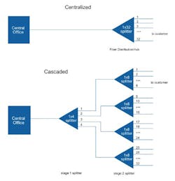
Centralized split architecture has been used extensively to reach subscribers in initial FTTH deployments. A centralized approach typically uses a 1x32 splitter located in a fiber distribution hub (FDH), which may be located anywhere in the network. The 1x32 splitter is directly connected via a single fiber to a GPON optical line terminal (OLT) in the central office. On the other side of the splitter, 32 fibers are routed through distribution panels, splice ports, and/or access point connectors to 32 customers' homes, where they are connected to an optical network terminal (ONT). Thus, the PON connects one OLT port to 32 ONTs.
However, as areas unserved by FTTH become costlier to build on a per-home basis, alternatives must be considered to reduce costs and speed deployment time. Hardened connectivity is one key to reducing deployment time. The other key solution is the use of distributed splitting.
Distributed split (cascaded) architecture
A cascaded approach may use a 1x4 splitter residing in an outside plant enclosure. This is directly connected to an OLT port in the central office. Each of the four fibers leaving this Stage 1 splitter is routed to an access terminal that houses a 1x8, Stage 2 splitter. In this scenario, there would be a total of 32 fibers (4x8) reaching 32 homes. It is possible to have more than two splitting stages in a cascaded system, and the overall split ratio may vary (1x16 = 4x4; 1x32 = 4x8 or 8x4; 1x64 = 4x4x4).
Distributed split approaches reduce the amount of fiber in the distribution area by moving a portion of the splitting process to the access point where the subscriber drops are connected. The 1x32 splitter in the primary FDH or fiber-optic splice closure (FOSC) is replaced by a 1x8 splitter, for example, and 8 fibers leave the FDH into the distribution network instead of 32. At the subscriber access point, one fiber is split to four outputs to the drops. A variation to this is to place a 1x4 splitter in the area entrance cabinet and 1x8 splitters in the access point. Either approach still delivers 32 connections to the OLT, but has achieved several important advantages:
- CommScope research shows that the FDH capacity can be reduced by 75%, allowing smaller cabinets, easier placement, and the prospect of moving from a cabinet to a splice closure.
- The distribution fibers required have been reduced by 75% as well, reducing capex for cable as well as for splice closures and splicing labor.
- The access point now includes a splitter, so a modest change here permits significant savings in the entire approach.
Star architecture
A star architecture pulls cables back to a central location using pre-terminated cabling, so it's very efficient from a splicing perspective. It uses about 35%-45% more cable than daisy-chained architectures and there can be more part numbers due to different cable lengths. While cable is often viewed as a relatively inexpensive part of the overall cost of an FTTH network, the extra cable required in the star configuration carries additional labor costs for deployment.
Star architecture can use a multi-port service terminal (MST), a component of hardened connectivity lines – it offers the option of not splicing any of the dropped fibers at the distribution point. It's called star because each terminal tail is brought back to a splice location. When used with centralized split, each cable going between the MST and splice case will have one fiber per terminal port. When used with distributed split, a single fiber between the terminal and splice case is used, and the terminal incorporates a 1x4 or 1x8 splitter. Distributed split architectures use about the same amount of cable as centralized, but the fiber counts are a fraction, and consequently the splicing costs are a fraction.
Daisy-chaining
Daisy-chaining can be a faster approach to deploy. It uses one cable and connects it through a cascade of fiber access terminals, leading to efficiency from a cable use and deployment labor standpoint. However, it may also require special splicing skills because it may need more splicing than the star architecture.
In fact, splicing labor is a key cost factor in FTTH deployments. In a star topology, fiber splicing is done at the hub, where individual cables are laid from the hub to each terminal. In a daisy-chained topology, fiber cable is run through the streets and a hardened terminal is spliced onto the cable; this design forces compromises in deployment time while increasing costs via the need for expensive, specialized splicing labor.
Splicing costs for centralized split, whether star or daisy-chain architecture, will be generally higher than for distributed split, as the splitter outputs are factory terminated. And fiber costs are lower for distributed split than for centralized, and generally lower for daisy-chained versus star architecture.
Fiber indexing
Fiber indexing is another alternative here. It uses connectorized cables and terminals, and enables installers to use a cookie-cutter approach to build out the network. A reduced set of cable lengths are daisy-chained together, limiting the need for custom cable assemblies or splicing. The basic building block, which is repeated throughout the service area, could be a 150-foot length of cable (for a majority of terminal locations), a terminal with a built-in splitter, hardened 12-fiber inputs and outputs, and four or eight hardened drops to the homes.
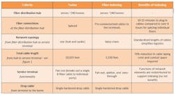
Fiber indexing has the potential to reduce construction and civil works costs in the distribution network by up to 70% and, in the process, significantly reduce deployment times and speed time-to-market. Table 1 compares fiber indexing with today's typical (centralized split) deployment model in a suburban network. One key savings lies in the length of cable needed, made possible by changing the network topology and consolidating the functions of multiple network elements into the service terminal. The other savings come from reduced splicing labor, minimizing site surveys, and reduced inventory management costs.
How fiber indexing works
Fiber indexing begins with a 12-fiber cable entering the first terminal (Figure 2). In the terminal, Fiber 1 is routed to a splitter for servicing local customers, and the remaining fibers are "indexed" or moved up as they exit the terminal to connect to the next terminal. Indexing means that the second fiber entering the terminal will exit as the first fiber to enter the next terminal, and so on in a daisy-chained fashion.
Traditional cascaded architectures require different terminals with different fiber lengths that require complex planning and custom cable orders, whereas fiber indexing uses a reduced set of cable configurations throughout the network. There are several variations of this architecture so it can meet requirements of different deployment scenarios. For example, it helps defer terminal costs and enables rapid installation when subscribers request services. By using approaches that eliminate splicing and can be installed more quickly, customers can be turned up faster and with lower overall installation costs.
There are several other advantages of fiber indexing:
- Flexibility without signal loss problems. There is little impact on signal strength, contrary to what might be expected from cascaded terminals. Low-loss hardened connectors maintain good link budgets, even to the end of the daisy-chain.
- Enhanced fiber utilization. By connecting the last terminal in the fiber run to any fiber distribution hub, the network can then feed the reverse path of each terminal's reverse port. This could then be connected to a subscriber's cable drop cable or be used to deliver other services at that terminal location.
- Streamlined inventory management. There are fewer part numbers, so inventory management and ordering are easier.
- Reduced or eliminated site surveys. Through the use of standard cabling parts, site surveys are reduced or eliminated.
- Trouble-free deployment. Factory-prepared cables and terminals prevent technicians from handling fibers and disturbing the signal during installation. Testing is also reduced versus conventional FTTH architectures.
All-splice vs. hardened connectivity
The various splitting alternatives and distribution architectures can generally be built with either all-splice or as hardened connectivity approaches. Clearly, moving the splicing function to an environmentally controlled factory will not only eliminate splicing costs in the field, and the associated expensive splicing equipment, it will also improve reliability, reduce opportunities for human error during construction, and reduce construction labor and time to deploy. The move to distributed split promotes cost reductions, and moving that into an indexing configuration provides even greater benefits.
Service providers will choose different architectures in their quest to deliver services rapidly and cost-effectively, but in the face of rising labor rates, distributed split architectures allow network operators to reduce overall labor costs and reduce deployment times by streamlining FTTH installations. As operators continue to expand their FTTH networks, these newer, hardened connectivity architectures will help improve business models and lead to speedier rollouts.
Fredric "Fritz" Amt, CommScope network architect, NAR Service Providers, has been supporting deployment of fiber-optic networks for more than 35 years. While working with CommScope over the last 10 years, Fritz has been building the FTTH market with CommScope passive and active products, supporting RFoG and xPON actives, and a variety of FTTH passive products. He earned his BSEE at Purdue University, West Lafayette, IN, and an MBA at the University of Connecticut, Stamford, CT. He is a member of IEEE and SCTE.


