Establishing a strategic optical-network T&M plan
With the telecommunications industry slowdown, network providers are searching for ways to address increasing bandwidth demand, reductions in revenue and staff, and quality of service (QoS) expectations. Part of the solution is to form a strategic testing plan for the optical network that addresses the test and measurement (T&M) issues at each phase of network development (fiber manufacturing, installation, DWDM commissioning, transport lifecycle, and network operation).
The right plan will optimize network performance and bandwidth for maximum network revenue generation. Forming a comprehensive strategic testing plan requires partnering with a strategic T&M company that has a complete understanding of the optical-network lifecycle and can offer solutions for each phase. During each phase, certain T&M requirements should be defined and obtained that address and assist the current deployment plan while anticipating upgrade and revenue generation plans.
A strategic testing plan for the optical network starts with the purchase of fiber cables that have been thoroughly characterized in fiber geometry, attenuation, and chromatic dispersion (CD) and polarization-mode dispersion (PMD). For instance, for lowest loss terminations at installation, it is critical that geometric properties such as cladding diameter and core/clad concentricity (offset) are well within specification. To maximize link signal-to-noise ratio, consistently low fiber attenuation is essential. In addition, while characterization of a fiber's dispersion characteristics may not be essential for every network, long link lengths and high bit rates clearly require the measurement of CD and PMD. Knowledge of the uniformity of all these parameters would also be useful to ensure that the network operates as expected no matter what sections of the purchased cable are used to construct the system.
Knowledge of these critical fiber geometry and transmission properties at early planning phases not only gives network operators the information they need to ensure current system operation, but also the data they need to determine the feasibility of upgrading the network in the future. Furthermore, knowledge of the longitudinal uniformity of some fiber properties, such as attenuation uniformity, gives assurance of the quality of the fiber cable, serves to help identify short-term installation stresses, and provides a baseline for long-term cable plant monitoring.
During the installation phase, a strategic testing plan should address loss, faults, and dispersion. For example, poor connector quality and polishing are the primary contributors to reflectance and optical return loss (ORL). Verifying connector condition during installation can be easily accomplished with optical microscopes. The new digital optical microscopes and advanced imaging software offer not only a method to verify cleanliness, but they also reduce user subjectivity and provide an easy way to document rarely seen characteristics.
In addition to reflectance and ORL, individual splice loss, fault location, and overall span loss can be determined with an optical time domain reflectometer (OTDR). In conjunction with a launch box, bidirectional multiple-wavelength OTDR measurements can identify potential problems before they affect service. In addition, the OTDR can be used to measure CD and qualify a fiber for Raman amplification.
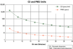
Two of the primary factors that limit optical-network bandwidth are CD and PMD, both of which cause the optical pulse to spread in time, resulting in a phenomenon called intersymbol interference. The spreading of the pulse will limit the transmission bit rate and distance and can result in bit errors and a reduction in QoS. Therefore, a strategic testing plan to accurately measure both types of dispersion is necessary to optimize an optical network (see Figure 1).PMD results from the two degenerate orthogonal polarization modes separating while the pulse traverses the fiber, resulting from a birefringent optical core. Birefringence of the core can result from the manufacturing process as well as external stress and strain from temperature changes, wind, and the installation of the fiber, making the magnitude of PMD statistical in nature and variable over time. Therefore, a thorough understanding of how PMD will affect the network and hence the QoS should be obtained via a strategic testing plan that calls for the measurement of PMD at different times of the day and different days of the year.
Adding more transmitting channels or wavelengths can increase the bandwidth of the fiber. Increasing the number of channels implies tighter channel spacing and the increased possibility of nonlinear effects, interference, and crosstalk. As a result, the network installer and network operator must ensure that each channel has the appropriate power level, optical-signal-to-noise ratio (OSNR), and operating wavelength.
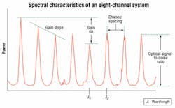
Commissioning of the network requires monitoring the spectral characteristics of the optical signals being transmitted. That can be done with an optical spectrum analyzer (OSA) during both commissioning and network operation. The OSA displays a graphical representation of wavelength verses power for each optical channel. In addition, the data should be presented in tabular form, identifying each channel along with its individual power level, wavelength, and OSNR. That allows monitoring of the wavelength drift and power levels as a function of time, which if left unchecked can cause interference and bit errors. Also, the OSNR for each channel, gain tilt, and gain slope can be monitored to ensure the proper performance of an erbium-doped fiber amplifier (see Figure 3).SONET/SDH networks are optimized for high-quality voice and circuit services, making them the dominant technologies for transport networks. To ensure an efficient SONET/SDH network and to validate QoS, a strategic testing plan for each of the three phases of the transport network lifecycle (installation, provisioning, and troubleshooting) should be implemented using SONET/SDH analyzers that have internal tools to clearly show the correlation between different alarm/error events.
The test plan for the installation phase includes verifying the conformity of the network through the validation of the functionality of the equipment, each network segment, and the overall network. That is done by performing network stress tests and protection mechanism checks, determining intrinsic limitations, and validating the interconnections between networks. In addition, validation of the quality of transport offered by the network is required and accomplished by gathering statistics on all error events that may occur during trial periods.
Provisioning of a SONET/SDH end-to-end path to implement a circuit is done by programming all the relevant network elements and validating the path. That includes verifying the connectivity path and determining the roundtrip delay.
Once the network is operating, troubleshooting and resolving failures or errors need to be done quickly since downtime and penalties are very costly. Depending on what kind of problem occurs in the network, fault isolation can be carried out very efficiently using a well-designed SONET/SDH analyzer that provides some advanced troubleshooting tools.
As capacity within MANs and SANs expands, a fast and economical protocol like Gigabit Ethernet (GbE) is required. GbE is an evolution of Fast Ethernet; nothing has changed in the applications, but the transmission speed has increased. Implementation into existing networks is seamless, since GbE maintains the same general frame structure as 10-Mbit/sec networks.
The GbE testing standard, RFC2544, defines the tests performed during network installation; statistics and nonintrusive tests are performed to assist in troubleshooting. Such tests include:
- Throughput, which defines the maximum data rate the network can support at a particular frame length without loss of a frame.
- Frame loss rate, which is the number of frames that are lost as a function of the frame rate.
- Latency, which is defined by the amount of time the data takes to traverse the network.
- Validation of the test requirements defined within RFC2544 will give network providers the ability to guarantee a certain level of QoS.
With networks becoming larger and more complex, network operators are faced with the daunting task of maintaining the network with fewer resources. A remote fiber test system (RFTS) gives network operators the ability to tackle the tasks of maintaining the network by performing around-the-clock surveillance of the network through the use of OTDR technology.
By defining a reference data set, the system continuously tests the network, compares results to the stored reference, and assesses current network status automatically. In the event of a cable break or fault, the system isolates, identifies, and characterizes the problem; determines the distance down the cable to the fault; correlates this information to a geographical network database to isolate the precise fault location; and generates an alarm report. In this manner, an entire trouble report, including probable cause and fault localization, is generated within minutes of the incident.
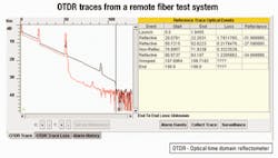
The data collected from an RFTS provides a benchmark from which to continually assess network quality. Through generation of appropriate measurements and system reports, operators can identify potential trouble spots, thus allowing for improved work-crew prioritization. The overall effect of early detection through an RFTS will be reduced operating costs through proactive network maintenance. In addition, the RFTS provides network operators the information to guarantee QoS and maintain service-level agreements (see Figure 4).Integration of all the T&M requirements into one strategic testing plan and one integrated platform will result in cost savings not only for the installer, but also for the network provider. One testing platform reduces the training time by eliminating the need to train each technician on different operating systems and allowing them to concentrate on the technology behind the test.
In addition, an integrated testing platform will reduce the testing time, decreasing the cost to deploy the network and allowing the network operator to generate revenue sooner. An integrated platform also provides a common point for all the data to be gathered during the manufacturing, installation, commissioning, transport lifecycle, and network-operation phases of the network. That will enable easy troubleshooting and bandwidth optimization during each phase of the network's lifecycle.
Dr. Kevin R. Lefebvre is product manager at NetTest (Utica, NY) and an instructor in the Telecommunications Department of the State University of New York - Institute of Technology (Utica). Harry Mellot is marketing communications supervisor, Stephane Le Gall is director of marketing and business development, Dave Kritler is marketing manager, and Steve Colangelo is a product specialist at NetTest.


