Production - Course in photonics automation 101
Engineers must deal with the '3Rs' of automation manufacturing.
MICHAEL FORMICA, Axsys Technologies
Years ago, the basis of our education was the traditional "3Rs" of "reading, 'riting, and 'rithmetic." Despite the marvelous advances of the computer age, the 3Rs still have a place in the ongoing education of engineers. With photonics proliferating all levels of the information superhighway, engineers must now learn the 3Rs of "reliability, resolution, and 'rchitecture."
As new photonic devices begin to leave the confines of the lab and enter mainstream production, there are many new factors to take into consideration when selecting automation equipment. The simple, manual, micro-meter-driven fiber-alignment stages used in the lab simply are not suitable for use in a manufacturing environment.
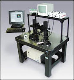
Instead, they will be replaced with sophisticated, computer-controlled precision automation equipment. However, all alignment systems are not created equal, and it takes an engineer well versed in precision automation to discern the difference between a motorized lab-grade system and a system designed for the rigors and demands of the production floor.
Consumers have an insatiable demand for bandwidth that fuels the need for expanded deployment of the optical layer. As fiber approaches the "last mile," the volumes of optoelectronic devices required will increase dramatically. To meet demand and maintain a competitive cost, manufacturers must optimize their automation investment. Downtime is not an option, as is evidenced by the semiconductor industry. Therefore, it is imperative that the selected automation platform be inherently reliable and robust.
While there are many products on the market that claim the ability to automate a fiber-alignment process, upon closer inspection, very few are suitable for production use. True, production-grade devices can withstand everyday use without any degradation in performance and require minimal upkeep.
Ball-screw mechanisms have been used for years in optoelectronic manufacturing. Their ease-of-use, good performance, and relatively low cost has made them a staple in the positioning system marketplace. The primary disadvantage of a ball-screw is in being a friction-based device and, as such, it will wear over time. As the screw wears, system performance will degrade in the form of increased backlash and lower accuracy, which adversely affects the quality of the parts produced on the machine. Despite regular maintenance, which requires additional machine downtime, ball-screws will eventually wear to a point where they will need replacement.For maximum system reliability and lifetime, a direct-drive motor system such as a linear motor or voice coil is recommended. Since these drive systems are noncontacting, they have no friction. As a result, there are no parts to wear, they require zero maintenance, they generate no particulate, and their performance characteristics are stable over time. Their unequalled reliability and robustness have made linear motors and voice coils the standard in high-performance semiconductor machines. Fiber-alignment and -automation machines based on direct-drive technology are the ideal high-performance, low-maintenance production tools.
Direct-drive motor systems also offer significant performance advantages. They are not only capable of significantly higher speeds than any other technology, but they also offer superior resolution-one of the critical parameters in fiber alignment.
Accuracy, resolution, precision, and repeatability are all terms often confused when specifying an automated alignment system. Of these, resolution is typically the most critical in optical alignments, yet it is also the one most commonly misunderstood. Resolution is, by definition, the minimum distance a positioning system can theoretically measure. That is often confused with step size, which is the minimum distance a positioning system can actually move.
Users should be wary of performance claims of 0.1-nm linear resolution or 0.05 arc sec rotary resolution, which are very misleading and typically not indicative of real-world performance. In a closed-loop system, resolution is a function of the capability of the feedback device, typically a linear or rotary encoder. However, actual step size is greater due to the effects of mechanical tolerances and servo performance.
A well-designed, closed-loop, direct-drive system will usually have a minimum incremental step size of two to three times the resolution. In an open-loop system, it can be much greater. Open-loop control systems have no feedback, so in those cases, resolution is defined as the theoretical smallest move the drive system can be commanded. Unfortunately, real-world effects, such as hysteresis, signal noise, friction, etc., make open-loop devices unsuitable for high-performance active optical alignment.
A common product is the piezo-based precision positioner that claims incredible resolution specifications. But upon closer inspection, those specifications are often referring to open-loop performance. While a piezo may technically be able to make a step that small, it is not a meaningful measurement. Amplifier and system noise must be tightly controlled since noise directly affects the stability of a piezo actuator. That is much more difficult to accomplish on a high-speed production line than in a well-controlled and isolated laboratory.
More important, piezo devices have inherent hysteresis. Therefore, upon reversal of direction, which is quite common in alignment applications, there is lost motion that effectively eliminates the advantage of fine resolution. To compensate, piezo devices are typically offered with a closed-loop position control option that effectively eliminates the backlash problem. It also results in a resolution specification much greater than that of the open loop.
While closed-loop control offers significant advantages over open-loop systems, users must be careful to evaluate the implementation of the closed-loop feedback devices to ensure they are getting the highest performance possible. The location of the feedback device-whether it be an encoder, linear variable differential transformer, strain gauge, etc., relative to the moving device-is critical.
Some of today's positioners use directly coupled, noncontacting feedback devices to derive positional information. Since the motor and encoder are directly coupled together, these devices offer greater performance than an indirectly coupled system such as a ball-screw, rotary motor, and encoder drive train. In those systems, rotary encoders measure the amount the motor shaft has moved, but that is not necessarily an accurate indicator of stage motion. Errors like screw backlash, coupling compliance, windup, and run-out contribute to degraded performance.
Further, the friction of the screw and mechanical compliance of the drive train make it nearly impossible to make consistent step sizes, which are critical in power peaking. Positioners using direct feedback have very consistent step sizes, allowing them to quickly and efficiently find peak power. While the implementation of the feedback device directly impacts alignment performance, there are many other system architecture considerations that become important once a process evolves to the manufacturing floor.
Nowhere is the difference between a lab device and production tool more obvious than with regard to system architecture. In the lab, devices are only used intermittently and with a much less critical eye than a production manager looking to maximize monthly shipments. While a lot of engineers enjoy the challenge of figuring out a new "toy," manufacturing is looking for an out-of-the-box solution that requires a minimal amount of effort to install. Most re searchers don't give a second thought to issues such as scalability, downstream integration, open-architecture, ease-of-use, and process throughput.
It is not uncommon to see several standalone control and instrumentation devices from various manufacturers strewn throughout a lab and connected by a slow general-purpose interface bus or RS-232 interface. These devices have dedicated functions and, though they may perform their specific task well, their scope is very limited. These single-purpose controllers, some of which have architectures dating back 10 years, are a throwback to the pre-PC days, and their performance can be equally archaic. A quick tour through a modern wafer fab will show that most automation is PC-based and the standalone architecture is almost nonexistent.
Today's most sophisticated automation tools are built around a high-speed peripheral component interconnect bus architecture that allows rapid communication from a host of devices such as machine vision frame-grabbers, motion controllers, data acquisition boards, and programmable logic controllers. A high-end software front-end is required to coordinate the numerous process steps, including:
- Automated parts database interface.
- Collision avoidance software during part loading.
- High-accuracy machine vision capture to ascertain part location.
- Submicron positioning control through active alignment algorithms.
- Coordinated triggering of epoxy dispense and cure or laser welding with post-weld adjustment corrections.
- Communication with shop-floor control.
Only advanced software packages are capable of running a production ma chine with this level of complexity. As advanced as these packages are, they can be equally easy to use, making them ideal for use in research, development, or production.
Nothing is more time-consuming or costly than having to redevelop a process or change vendors. Most suppliers serving the laboratory market are only capable of providing either component-level solutions or custom machines.
The ideal supplier can offer a wide range of standard solutions, from component-level to full-scale turnkey automation. By using a single vendor for both laboratory and production, users are able to migrate from the lab to production much faster, greatly improving their time-to-market.
Only with full automation of photonics manufacturing will device suppliers meet the never-ending demand for more bandwidth. As new devices and technologies are created, companies that can quickly migrate a product from the researcher's bench to the production floor will be the next industry leaders.
Michael Formica is general manager of Axsys Technologies Inc.'s fiber automation division (Pittsburgh). He can be reached via the company's Website, www.axsys.com.
Accuracy. Difference between the actual position in space and the desired location against an absolute reference.
Resolution. Minimum distance measured by a closed-loop feedback device. Resolution does NOT imply the ability to physically move a given distance (step size). Rather, it is a measure of the encoder resolution only, which does not include effects such as backlash, hysteresis, and wind-up.
Step size/minimum incremental motion. Smallest possible physical movement of the system. Step size is always greater than resolution.
Repeatability. Ability of a system to return to a given point in space over many attempts. It can be either bidirectional (return to the point from any direction) or unidirectional (from one direction only). Bidirectional repeatability is much more difficult to achieve since it takes into account the effects of backlash and hysteresis.

