Depolarizers enjoy increasing demand in long-haul and EDFA markets
Users must assess the applicability of various depolarizer types and address the issues of each.
FRANK JUNG and KEVIN SHIRK, Alliance Fiber Optic Products Inc.
There is high demand for depolarizers in today's telecommunications architectures, particularly in the long-haul telecommunications arena. Market demands also come from the optical test-instrumentation manufacturers. The reasons for such demands in the former are due to the wide-ranging applications of erbium-doped fiber amplifiers (EDFAs). The issue of polarization-dependent gain (PDG), often called polarization hole-burning, arises when the number of EDFAs in the system increases to the hundreds.1 In the latter case, the issues are polarization-sensitive components such as mirrors, gratings, prisms, and optical detectors.In long-haul optical telecommunications, one area of intensive study is signal-induced PDG arising from EDFAs.1 The basic problem is that the gain of the EDFA is higher in the direction orthogonal to the signal. That's due to the environment of the erbium ions, allowing preferential interaction in this direction.
Since the signal normally experiences gain in the saturated regime of the EDFA, the component of the amplified spontaneous emission (ASE) in this orthogonal direction will, therefore, experience relatively more gain than the signal. Thus, ASE accumulates a bit for every EDFA. Since ASE is basically unwanted noise in this case, a system with many EDFAs could gain sufficient ASE to eventually degrade the signal-to-noise ratio to unacceptable values.
There also exists a pumped-induced PDG effect. A signal with polarization aligned along an axis "presumably defined" by the polarization of the pump1 experiences higher gain than an orthogonal alignment. The time-averaged effect is similar to polarization-dependent loss (PDL). PDG can be practically eliminated by depolarizing the signal, which several international research groups have demonstrated in long-haul systems.14,15,16In the area of optical measurement, numerous applications abound, including the minimization or elimination of PDL from the devices under test (DUTs). All laser sources are highly polarized. Consequently, in testing setups using such light sources, DUTs whose parameters of interest are highly dependent on source polarization, could exhibit undesirable PDL. One method of minimizing PDL from DUTs is the addition of a depolarizer in line with the laser source.
Since a depolarizer is an ideal source of a complete set of states of polarization (SoP), one can take advantage of this property to measure PDL rapidly. Another benefit would be the reduction of PDL-induced error caused by polarization-sensitive components, such as detectors, mirrors, diffraction gratings, or external optical modulators. Polarization simulation is also possible, such as in testing telecommunication systems when random polarization states are required.
Along with various types and applications, those with current and future needs must know the related issues concerning each and how to assess the applicability of the various types of depolarizers in today's market. In discussing the fundamentals of depolarizers and their current and potential applications, the conceptual basis will be emphasized at the expense of mathematical rigor.
Fundamentally, there are no current devices that can completely depolarize light. If we take a section of a beam of light short enough in the time domain, the light will always have a state of polarization. Beam of depolarized light is ideally averaged and has no particular polarization state. The "averaging" term is meant to imply time averaging of the various polarization states, so that the polarization appears scrambled. Therefore, devices avail able in the market are only pseudo-depolarizers. For now, we will adhere to the term "depolarizer" to mean "pseudo-depolarizer."The differences among the various depolarizers are in the averaging process of the various polarization states. These categories include spatial averaging (i.e., crystal depolarizers), spectral averaging (i.e., crystal Lyot depolarizers), and temporal averaging (i.e., piezoelectric phase modulation, re circulating loop approach, and electro-optical modulation). Let's examine more closely the basis of operation for each category of depolarizer.
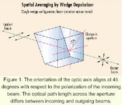
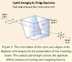
In spatial averaging, a crystalline material, such as quartz, is cut to a wedge whereby the optic axis of the material lies on the plane of the wedge. The orientation of the optic axis is aligned at 45 degrees with respect to the polarization of the incoming beam (see Figure 1). Due to the wedge geometry, the incoming beam experiences different optical path length across the aperture of the outgoing beam.
As a result, a phase gradient is established along this transverse direction, effectively generating a retardation plate with a variable retardation across the aperture. Consequently, incoming beams with a particular plane polarization state no longer retain this particular state. The various retardations generate a variety of polarization states, all spatially averaged in the outgoing beam.
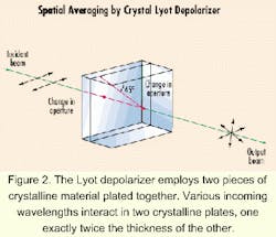
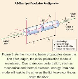
The original design of the Lyot depolarizer employs two pieces of crystalline material, such as quartz plates assembled with their optic axes lying in the plane of the plates and oriented at 45 degrees with respect to one another (see Figure 2). One plate is exactly twice the thickness of the other. For the incoming beam to be depolarized, it must have a range of wavelengths. The spectral averaging occurs due to the generation of a varying amount of circularly and elliptically polarized light as the various incoming wavelengths interact in the quartz plates. The dispersion property of the quartz material effectively governs the amount of phase shift according to the wavelengths. That generates a spectrum of state of polarizations in the outgoing beam, all averaged spectrally. A formal treatment has been published.2Conceptually, depolarization takes place this way: As the incoming beam propagates down the first fiber (length L1), the initial polarization mode is maintained. However, due to random perturbation such as mechanical and thermal stresses, energy from one mode will leak to the other as the lightwave continues down the fiber. Eventually, the energy in all the polarization states will be equal ("depolarized" light) at a sufficiently long distance compared to a correlation length lc of that particular fiber. If the angle qp is set to 45 degrees, depolarization is theoretically complete (i.e., output is randomly polarized). But to ensure that to be the case in practice for any qp, the length L2 should be at least twice the length of L1 (for Lorentzian- or Gussian -shaped sources) or a multiple value of L1 (for re c tangular-shaped sources).4
In practice, the values of L1 and L2 are also determined by the spectral width Dl of the light source and the PMD of the fiber. PMD (units of psec/km) is related to the phase shift (or group delay) between the orthogonal polarization states, whereas Dl is related to the coherence time tc or coherence length Lc of the light source. For depolarization to be independent of the rotation angle qp, and so no overlap occurs in the coherent regions in the second fiber, the coherent length Lc must be much smaller than the orthogonal modes' spatial separation (due to PMD) in the first fiber and about half that separation in the second fiber length.
Another technique involves modulating the polarization phase delay between the two orthogonal states of a monochromatic light down either a polarization-maintaining fiber (PMF) or singlemode fiber.6,7 Since the SoP depends on the relative phase of these orthogonal modes, the SoP of the output varies at the modulation frequency. Applying a sinusoidal voltage to a piezoelectric transducer wrapped with the optical fiber to be stressed provides this modulation.
In the case of PMF, by temporal averaging of the SoP output at a frequency lower in comparison to the modulation frequency, the degree of polarization (DoP) can be shown as a Bessel function of zero order whose argument is the phase amplitude of the modulation. Hence, the DoP becomes negligibly small as the phase amplitude approaches the zeros (e.g., 2.4, 5.5, 8.7,...radians) of the Bessel function.
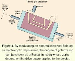
Another approach of modulation, known as electro-optical modulation, takes advantage of the electro-optical properties of the uniaxial crystal lithium niobate LiNbO3.6,18,19 This crystal possesses the physical property by which the values of its various refraction indices can be modulated by an external electrical field. The relative change of these indices depends on the components of the electrical field along the crystal axes. Hence, by sending a beam of polarized light whose components are decomposed equally along orthogonal axes of a Z-cut crystal (i.e., TE- and TM-polarized modes), a phase-shift difference appears between these orthogonal field components when an external electrical field is applied. By modulating this external field, the DoP can be shown as a Bessel function whose zeros depend on the drive power applied to the crystal. Hence, DoP can theoretically approach zero (see Figure 4).
The recirculating ring approach to polarization averaging was recently patented. This passive depolarizer is based on averaging the incoherent polarization states of a lightwave recirculating through couplers.8 Although the concept of employing a recirculating delay line had been demonstrated using PMF,9 the additional concepts of using non-PMF, narrow-bandwidth sources and additional recirculating loops facilitated the practical implementation of this device.10,11,12,13
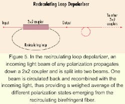
The conceptual basis of the recirculating loop depolarizer (see Figure 5) involves an incoming light beam of any polarization state propagating down a 2x2 coupler and being split into two beams. One split beam is circulated back by one of the coupler output fibers and recombined with the incoming light. This recombination provides a weighed average of the different polarization states emerging from the recirculating birefringent fiber. There is no longer a preferred polarization. Hence, a linearly polarized input beam will emerge with its degree of polarization depressed. Using this concept, the degree of polarization can be further decreased to any practical values by concatenating several such 2x2 couplers with recirculating loops.
In practice, the realization of the potentials of this near-ideal depolarizer is limited by several factors:
- The spectral width ΔLambda of the laser sources set a limit on the coherence time tc and thus the coherence length Lc = ctc of the lightwave. Coherence time tc may be considered as the memory time of the lightwave. A large tc means a wave of constant amplitude of long length. If Lc is longer than the recirculating loop length L, then the incoming light will interfere with the recirculating light at the input of the coupler. This interference effectively defeats the purpose of DoP minimization since constructive interference could give rise to large amplitudes for preferential polarization states. In practice, to minimize interference, L must be larger when compared to Lc.
- The bending loss of the fiber sets a limit to the size of the recirculating loop and, therefore, to the device itself. Bending loss can be understood as an energy transfer from the core to the cladding of the bent fiber. If the angle of incidence of the singlemode beam is too close to the norm of the core-clad interface, total reflection can no longer be sustained. Some of the light energy is then transferred to the cladding, leading to an effective increase of insertion loss (IL). In applications with limited power budget, large IL values could not be tolerated. To minimize IL, the bending radius must be larger than the critical bending radius Rc of the fiber in question. For bare singlemode fiber, Rc 50 mm would be a safe value.
- The PDL of the depolarizer must be considered. PDL is defined as the difference between the maximum and minimum light attenuation through a devicefor all SoP. The optical transmission of some devices, such as the couplers used in the fabrication of re circulating-loop depolarizers, depends on the polarization states of the incoming light. Hence, if light were vertically linearly polarized, its power loss may be less than the horizontal component. Light that fluctuates between these two polarized states would fluctuate in power, as well. Ideally, the PDL of the depolarizer should be as small as possible to maximize the signal-to-noise ratio of the output.
- For certain applications that require constant power throughput, the optical power stability (OPS) of the depolarizer must also be considered. OPS (units of db/time) is the maximum optical power output variation for a given duration. It may be viewed as a figure-of-merit of the mechanical and thermal stability of the depolarizer under various operating conditions. It reflects the design and fabrication integrity of the depolarizer.
Each of the various depolarizers has inherent advantages and disadvantages that must be assessed in terms of the application being considered. Crystal depolarizers, for example, have the advantage of cost-effectiveness, but their use is confined to only broadband source, or super-luminescent, diodes.
Non-crystal Lyot depolarizers enjoy one main disadvantage-the necessity of a power source, which consequently sets a limit on the cost, size, and reliability. However, the degree of depolarization and the amount of IL possible are highly competitive. A wide range of wavelengths can also be accommodated.Due to the waveguide structure required in their design, the cost of electro-optic depolarizers is relatively high not only from a material point-of-view, but also because of the power requirements. In addition, LiNbO3 limits the useful wavelengths to only the 1,550-nm band. The overall fiber-to-fiber IL is about 3 dB. In practice, to reach low DoP values such as 2%, precise fiber orientation alignment (tolerance of 1 degree) and highly stable drive power are required.18 However, DoP varies linearly with wavelength from 15% at about 1,460 nm to about 2% at 1,560 nm.18
The recirculating delay line depolarizer combines the advantages of the crystal and non-crystal Lyot depolarizers. Being a passive device since mechanical modulation is not required, external power sources are eliminated and reliability is increased. The elimination of power sources and PMF make this device cost-effective.
The device is also light and compact, largely due to the elimination of power sources and modulators. It can accommodate a wide range of wavelengths, including the commonly used bands like 980, 1,550, and 1,310/1,550 nm. Additionally, it possesses light-source spectral-bandwidth accommodation from the most common laser sources-practically any bandwidth from 0.01 nm and up.
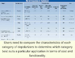
Clearly, there exists a market demand for depolarizers. But are they available to meet this demand? The Table summarizes some of the characteristics as well as the relative pricing of the depolarizers just discussed. Apparently, a wide range of wavelengths can be met. However, it is not known whether more stringent requirements from the long-haul telecommunication arena could be met. Currently, a tradeoff may be necessary, for example, between OPS and insertion loss or between a passive versus active device.
Along with the growth of the optical-telecommunications arena, the demand for depolarizers of compact size, highly reliable, low-cost, and improved specifications will inevitably increase. This demand drives the development of depolarizers by incorporating newer technologies such as integrated optics and micro-electromechanical system (MEMS) technologies.
Frank Jung, Ph. D., is a senior engineer, and Kevin Shirk is product manager at Alliance Fiber Optic Products Inc. (Sunnyvale, CA).
- Becker, R.C., Olsson, N.A., Simpson, J.R., Erbium-Doped Fiber Amplifiers: Fundamentals and Technology, Academic Press: New York (1999), pp. 359-361.
- Billings, B.H., "A Monochromatic De polarizer," Journal of the Optical Society of America 41: 966-975 (1951).
- Böhm, K., Petermann, K., and Weidel, E., "Performance of Lyot De polarizers with Birefringent Single mode Fibers," Journal of Lightwave Technology , LT-1:71-74 (1983).
- Burns, W.K., "Degree of Polarization in the Lyot Depolarizer," Journal of Light wave Technology, LT-1:475-479 (1983).
- Poole, C.D. and Nagel, J., Optical Fiber Telecommunications, IIIA, Kaminov, I.P. and Koch, T.L. (eds.), Academic Press: New York, (1997), pp. 114-124.
- Kersey, A.D., Dandridge, A., and Marrone, M.J., "Single-mode Fiber Pseudo-depolarizer," Fiber Optics and Laser Sensors V, DePaula, R.P. and Udd, E. (eds.), Proc. SPIE 838:360-364 (1987).
- Chien, P.Y. and Pan, C.L., "Fiber-optic Gyroscopes Base on Polarization Scrambling," Opt. Lett. 16:189-190 (1991).
- U.S. Patent No. 5,933,555 issued to Pai-Sheng Shen.
- Lutz, D., "A Passive Fiber-Optic Depolarizer," IEEE Photonics Tech nology Letters, 4:463-465 (April 1993).
- Shen, P. and Palais, J.C., "New Single-Mode Fiber Polarization Scrambler," Optical Fiber Technology, 3:184-188 (1997).
- Shen, P., Palais, J.C., and Lin, C., "Tunable Single-Mode Fiber Depolarizer," Electronic Letters 33: 1077-1088 (1997).
- Shen, P., Palais, J.C., and Lin, C., "Fiber Recirculating Delay-Line Tun able Depolarizer," Applied Optics 37: 443-448 (1998).
- Shen, P. and Palais, J.C., "Passive Single-Mode Fiber Depolarizer," Applied Optics 38:1686-1691 (1999).
- Bergano, N.S., Mazurczyl, and Davidson, C.R., "Polarization Scrambling Improves SNR Performance in a Chain of EDFAs," Conference on Optical Fiber Communication, Vol. 4, OSA Technical Digest Series (Optical Society of America, Washing ton, D.C.), 255-256 (1994).
- Taylor, M.G. and Penticost, S.J., Electronic Letters 30:805 (1994).
- Fukada, Y. and Imai, T., and Mamoru, A., Electronic Letters 30:432 (1994).
- Bruyere, F., Audouin, O., Letellier, V., Bassier, G., and Marnier, P., IEEE Photonics Technology Letters 6:1153 (1994).
- Heisman, F., Korotky, S.K., and Veselka, J.J., Optical Fiber Telecommunications IIIB, Kaminow, I.P. and Koch, T.L. (eds.), Academic Press: San Diego (1997), pp. 377- 436.
- Heisman, F., "Compact electro-optic polarization scramblers for optically amplified lightwave systems," Journal of Lightwave Technology, 14:1801-1814 (1996).
