Trends in fiber-optic module assembly
Kevin Closson Gould Fiber Optics
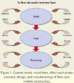
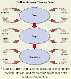
Fiber-optic component suppliers increasingly must build modules and subassemblies for their original equipment manufacturer (OEM) customers. While not new, this trend continues to accelerate for a number of reasons-the push toward integrated supply chains, more complex systems, and tighter specifications, among others. Many component suppliers have stepped up to fill the gap in this market as specialization and management decisions drive some OEMs to concentrate on core competencies rather than the manufacturing of each piece of the system.For component suppliers that expand into building subassemblies for OEMs, there is a distinct product path-from concept to design to the manufacturing phases (see Figure 1). Emerging trends within each of these phases drive the subassembly process.
During the concept phase, contact is made between the customer and the supplier and ideas are fleshed out. Whether the supplier or customer makes this initial contact, key decisions must be made before the process can proceed. Frequently, customers are unsure of which suppliers can meet their needs. As a result, this phase can be long and tedious. By letting potential customers know which services can be rendered, component suppliers ease this process.
After initial contact is made and the customer is reasonably comfortable that the supplier has the capabilities required, several key things occur. The basic functionality of the module is established. Questions such as the extensiveness of the design, what level of subassembly is to be provided, when, and at what price, are examined. Often, customers find a 3-D visualization of the device extremely helpful and, in some cases, necessary. Several off-the-shelf computer-aided-design (CAD) packages can provide this visualization. Many customers are so pressed for time that a physical prototype is not an option.
Once the functionality of the device is established, other questions arise that must be answered. What is the footprint for the device? Will it be disposable for the customer, or repairable? What other organizations and companies will be involved with the assembly? All these questions require answers before a final decision can be reached on whether or not the supplier will build the subassembly and design can proceed.
During the design phase, many of the important trends in subassembly work manifest themselves. Here, issues such as interconnection, integration, and make-buy decisions are critical to the success of the program.
One key decision during the design phase is interconnection of the unit with other subassemblies. Options range from free-space beam transmission, to fusion splicing, to physical contact connectors.
As old limitations on power transmission and components are exceeded, free-space transmission is becoming a viable option for many OEMs. In these systems, alignment of fibers, lenses, and components is crucial. Methods such as flip-chip and etch-stop alignment are commonly used techniques. However, while it is gaining in importance, free-space beam transmission is still not a commonly used interconnection technique because of its strict requirements.
Fusion splicing is well established as an interconnection method. Modern systems automatically align and fuse fibers with losses of typically less than 0.05 dB. The permanent nature of splicing limits its applications, however. If a subassembly needs to be replaced, reworked, or updated, it is often necessary to break the interconnecting splices. This task is time-consuming and/or infeasible for many modules. Nevertheless, fusion splicing retains prominence in subassembly interconnection because of the low losses achieved and its protective nature.
The final technique for module-to-module interconnection is the use of connectors. Common physical-contact fiber connectors come in a wide variety of shapes and sizes. As module sizes get smaller and smaller, connector size plays an increasingly important role. Small-form-factor (SFF) connectors are quickly becoming the standard and where the component is deployed may influence connector choice. The MU by NTT is well established in Japan, the Diamond E2000 may prove popular in Europe, and Lucent Technologies' LC is among the widely accepted SFF connectors in the U.S. market.
The use of backplane connectors is another emerging trend for assemblies. Usually found on plug-in cards, these connectors are used much like an electrical backplane connector.
The trend toward smaller modules is also fueling the expanded use of ribbon fiber, and, consequently, ribbon connectors. These connectors utilize precisely cut V-grooves to align an array of fibers in a ceramic ferrule. Up to 12-fiber ribbons can currently be accommodated.
During the design phase, the packaging of the assembly requires special consideration. As space on cards, racks, and even within modules shrinks due to component density, packaging plays a more important role in design. Issues that optical engineers used to ignore now matter. For example, electro-magnetic interference (EMI) or crosstalk found in electrical assemblies can be exacerbated when the addition of optical components shrinks the distance between electrical components. Similarly, electro-static discharge (ESD), always important in electrical systems, is now critical as optical and electronic technologies merge within subassemblies.
Today, the module designer has greater options in packaging. Increased use of dissipative plastics to encase components is evident. This type of plastic is impregnated with material that allows it to slowly disperse static charge so that the electrical components inside are not damaged. Heat dissipation as a result of density, increased laser-transmission power, and other factors, is a concern for some modules. Some applications require a hermetic seal to mitigate environmental factors. Finally, weight may have to be minimized in some systems. All of these issues must be taken into account when designing subassemblies.
Greater distances between signal regeneration in long-haul transmission raises new concerns about once-neglected optical effects. Delay propagation and polarization-mode dispersion (PMD) are leading to tighter tolerances in lead lengths between components inside and outside of subassemblies. Customers that once asked for lead-length tolerance between two optical paths in a system of ±10 cm now routinely demand intra-fiber tolerances on the order of ±2.5 mm. Such requirements force designers to consider manufacturability issues and may radically alter how modules are built.
Two themes appear central to many of these design issues: increased component density and the combining of optical and electronic components into hybrid devices. It's hard to tell which issue is driving the other. As component density increases, the line between the optical component on a board and the electronic one becomes blurred. On the other hand, more modules can be packed onto a single card as this integration continues.
Regardless of which trend pushes the other, the designer must be cognizant of these issues. Traditional optical-component suppliers are being asked to straddle the line and become experts in electronics. This expertise may be as simple as integrating a laser with a tap coupler for monitoring purposes or as complex as the addition of a printed circuit board (PCB), fully populated with circuitry, to an optical module.
Among the myriad decisions made by the designer are the more traditional "make-buy" decisions. Optical component suppliers cannot become instantly knowledgeable about the construction of a PCB, for example. Sometimes the knowledge is there, but the physical facilities are not. These realities drive important decisions on which vendor will supply these subcomponents. When a supplier does not make all the components that compose a module, quality must be assur ed. This assurance can come in the form of additional testing after assembly, prescreening of the supplied components, and strict adherence to quality standards. In the end, though, the customer must be confident that the device paid for is delivered with the functionality required.
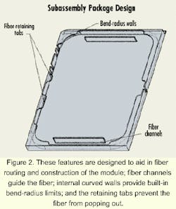
No matter how good a concept is, or how thorough the design is, manufacturers must be able to build the product. Failing to consider the production of the device during the concept and design phases can come back to haunt the manufacturer. As component suppliers develop modules with higher functionality, they must pay attention to industry trends that can affect manufacture such as fiber routing, increased testing, and price and time pressures.Fiber routing is a crucial step for makers of subassemblies. Because of minimum bend radius requirements, how and where optical fibers are placed within a module plays a critical role in manufacturing of the device. High component density within the module makes the routing more difficult. Subassembly packaging can be designed to make it easier, however. Fiber channels using the package walls to limit bend radius and retaining tabs can all simplify routing (see Figure 2).
Fiber routing is even more important when a long length of fiber is required within the module, as is the case with erbium-doped fiber amplifiers. In other modules, less fiber is required, but service loops are still commonly used in case repairs are necessary inside the assembly. Regardless of how much fiber is within a module, its routing must be carefully planned and executed during the assembly phase.
Component suppliers that move into the subassemblies business typically know that additional testing is required. Even if the only components used in the module are common and easy to test, two trends have emerged that affect optical subassembly manufacture. First, customers are demanding more thorough and complex testing of devices. Secondly, suppliers either buy components from other sources to include in modules or develop new components for their own use. These new components introduce another variable into the testing equation for suppliers.
As customers begin to demand test data on effects such as PMD, wavelength dependence, and temperature dependence, suppliers must be capable of providing it. Every module will not require every test, of course, but no supplier wants to turn away work because of an inability to test the completed device. Having a broad testing knowledge and adequate test facilities is imperative for subassembly suppliers. However, customers must know that the level of tests affects the cost of the module. A simple battery of tests may cost significantly less than a full characterization of the module. The list below indicates some of the optical and electrical tests common to these modules:
- Optical tests-insertion loss, return loss, PMD/polarization-dependent loss (PDL), wavelength-dependence, flatness.
- Electrical tests-responsivity, jitter, dark current, switch speed, output power.
Testing of supplied components is something every manufacturer, in any industry, must face. For fiber module suppliers, the question is when to test. Two options readily present themselves: test each component before assembly of the finished product or test the entire unit once it is complete. Each option has its advantages and disadvantages. The testing of each component going into a module is time-consuming and costly, even on a sampling basis. Additionally, a component that passed the tests could be damaged during module assembly. On the other hand, it is extremely difficult and costly to try to find the source of a problem during post-assembly final testing. The question of when to test components has no easy answer. Manufacturers of fiber subassemblies must carefully weigh the costs and benefits of when to test. Often, a mix of the two is appropriate.
The manufacture of fiber modules is not, of course, done in a vacuum. There are always business concerns that drive the assembly process. Cost and delivery are chief among them. As customers provide an opportunity for agile suppliers to offer more extensive subassemblies, they also demand these modules at lower costs. The customer probably has the in-house knowledge of how to build the module, but decides to contract it out for any number of reasons; the company may not have the equipment or expertise in manufacture or may wish to focus its resources elsewhere, for example. However, customers very often know what components go into making the device and their market price. As a result, customers have tremendous leverage to demand lower prices. Thus, effective suppliers need to be efficient and cost-conscious without sacrificing quality.
Perhaps even more important in today's market are lead times. The expression, "whoever gets there first wins the business," is truer than ever. Many customers will pay a premium to the supplier that can arrive first with the desired solution. Thus, agile suppliers that can compress the design and manufacturing cycle may win the new business.
As component suppliers expand into the realm of subassembly work, these companies must follow the trends developing in the field. Many OEM customers are asking for a "black box" that has specific functionality. Suppliers seeking to gain this business must recognize the needs the customer has and respond. Trends like smaller size, increased integration of optical and electrical components, tighter tolerances, and more testing requirements in addition to cost pressures and shortened prototype-to-production cycles time threaten to push suppliers to their limits. However, fiber-optic companies that step up and respond to the challenge will have the opportunity to become key suppliers to major OEMs-and increase their bottom lines.
Kevin Closson is a product engineer at Gould Fiber Optics (Millersville, MD), where he designs and implements integrated optical solutions for Gould's customers. He can be reached at [email protected].


