Automated alignment equipment in test and measurement
To retain a competitive advantage, manufacturers must efficiently ease the bottleneck for test and measurement of optical components.
DR. STEPHEN KIDD, Melles Griot
As the photonics sector of the telecommunications industry continues to grow at an unprecedented rate, active and passive optical-component manufacturers struggle to keep pace with rising demand-and the testing and measurement of these component devices frequently appears as a bottleneck. To remove the bottleneck, investment in factory space (usually an expensive clean-room-quality area), capital equipment, and staff are essential. The efficiency by which a manufacturer can ease the test and measurement bottleneck is important and could be vital in retaining a competitive advantage.
Like many of the steps in a manufacturing process, the testing and measurement of components requires a diverse array of equipment to be deployed and operated in unison. In addition, manufacturing process steps cannot be viewed or assessed in isolation, which means that certain steps need to be considered before and after testing.
Some manufacturers choose to test their components with the same equipment that pigtails or permanently assembles some part of the product, once the components pass required tests. This approach may be advantageous since the final product yield should be high. However, the downside is that it would have been quicker to test 50 or 100 of the components together on the same wafer or bar. There are many subtleties to be considered on the path to a fully optimized manufacturing operation.Central to the test and measurement of nearly all optical components is precision positioning. Many of the critical parameters of a device can only be determined when singlemode fiber(s) have been temporarily aligned and optimized. Fiber alignment-particularly rapid, automated alignment-is a central underlying requirement for most photonic component testing.
Successful selection and implementation of test and measurement systems require some understanding of alignment technologies. The main features include speed; search efficiency; alignment reproducibility and stability; robustness and durability; integration and partnerships; flexibility; and service and support.
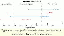
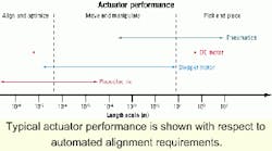
Alignment system efficiency is dictated by translation and rotation stage design, actuators, and alignment methodology. Translation and rotation stage velocities are perhaps the most visible and obvious indications of an alignment system's overall speed. But things are not always that simple. In essence, an alignment system operating at the heart of a component test and measurement system has three distance scales of motion to consider, each scale separated by three orders of magnitude:
The Figure shows how these three scales overlap the performance of common actuator technologies. The distance scales are so disparate that no one stage and actuator technology can deal efficiently with all of them. Pneumatically driven stages are among the fastest for long travel, but their precision is far removed from that required for fine adjustment.
The fact that direct-current (DC) motors span all three required motion scales is the single best reason for their widespread use in the photonics test and measurement sector (as with component assembly and pigtailing). However, their efficiency at making small, incremental submicron motions is not great.
Stepper motors are generally not as fast as DC motors, and their use for long travel motion is limited. In their typical open-loop operation, resolution is not as high as with DC motors. To make rapid, precise, and repeated submicron motion, peizoelectric actuators outperform most other actuator technologies. But their limited range of travel means they must usually be combined with some other longer travel actuator as a hybrid solution.
Analysis of a typical test and measurement alignment subsystem usually reveals that a significant amount of time is taken to perform a search (sometimes referred to as a "blind search"). The objective of this search is to obtain some initial coupling of light, sometimes called "first light," between components. This search time is on the order of tens of seconds (or less) for active components such as diode lasers. Searches are usually over a two-dimensional space, with the search time scaling with the area to be searched. If component-to-component positional variability is low, the search area can be small, with a correspondingly low meantime to achieve initial coupling.
For many passive components and the infamous "dark waveguide" configuration typical of Mach-Zehnder waveguide modulators, the time to search and obtain initial coupling can be as long as minutes. That's because the search time scales with the square of the area of the search at just one end of the device-it is really a four-dimensional space that is being searched. Even with efficient search patterns such as combined two-dimensional spirals or four-dimensional hyperspirals, blind searching for initial coupling can be a slow, time-consuming process.
To obtain efficient searching, the search area must be as small as possible. Machine vision, with associated feature extraction, represents an effective way of pre-positioning components prior to any active search to obtain initial coupling. In certain circumstances, a machine-vision system can accurately pre-position components (e.g., fiber to waveguide) to within a few microns, obtaining initial coupling without the need for any searching. All that remains is for the alignment system to optimize the coupled light.
Currently, two methods or principals dominate alignment techniques: numerical and active. The numerical technique relies on building an accurate map of component coupling versus position. The map can be multidimensional and cover significant areas, but with the attendant rise in the time required to acquire the map data. Once acquired, numerical processing of map data reveals the optimum coupling position of the components. The stages can then be commanded to go to that position. The numerical approach has high reproducibility and does not require initial coupling of light between components. However, the technique can be slow to implement (particularly if suboptimal actuators are used) and cannot compensate for any dynamic change in component position that may occur. If a component does move, the entire mapping and peak-seeking process must be repeated.
Active alignment is achieved by creating a feedback loop linking the coupled power and component position. Within this loop, small amplitude dithering of one component with respect to the other is used to determine which direction to move to increase coupled power. By controlling the amplitude of the dithering (which can be as small as tens of nanometers) and the gain parameters of the feedback loop, good system response times of as low as 1 sec can be achieved as well as stable behavior once maximum coupling has been obtained.
Active alignment does require some initial coupling of light and risks finding only a local maximum in the coupling between components, though this is not usually an issue for Gaussian-like coupling variation with position. Active alignment also has the benefit of adapting and automatically compensating for dynamic changes in component position. The alternative strategies for component alignment-passive and vision-guided-are likely to become more prevalent over time.
In a test and measurement system, the component alignment mechanism is likely to constitute the only set of moving parts (excepting items such as motorized gratings inside optical spectrum analyzers). The alignment system, therefore, has the highest potential for equipment failure, malfunction, or susceptibility to wear and tear.
Consequently, careful selection of alignment mechanism components is required. Stages, actuators, controls, and software should be selected on the basis of their applicability to the tasks requested of them. For stages, if long travel (more than a few millimeters) is required, then ball or roller bearing stages are the only choice. While roller bearings are often seen as the only choice because of their precision and smoothness of travel, they do exhibit some detrimental characteristics. For example, high pre-load tensions tend to reduce and creep over time, and any particulate contamination on the bearing rails tends to be rolled firmly into place.
For short travel stages, flexures not only offer the best performance (smoothness of travel, resolution, repeatability), but in terms of durability, they suffer no detectable loss of performance over time. Consequently, servicing and overhauling are negligible. Flexure stages do not provide true rectilinear motion-a small parasitic arcuate ("bow-like") motion is superimposed. However, this is small and usually negligible compared with the precision with which the axes of a true rectilinear stage will be aligned to the optical axis of the component being aligned. For applications where accurate mapping is required, the arcuate motion of the stage is easily de-convolved because it is deterministic.
There are also comparable tradeoffs with actuators. Precision DC motors and linear encoders require very careful handling as well as routine calibration. There are many subtleties to their control, particularly regarding the servo behavior when the stage is nominally at rest. Stepper motors generally are more robust and hold static position well. Sometimes, an encoder also may be present, but only in situations where there could be doubt about the motor's micro-stepping capabilities.
Given the diverse test and measurement requirements of photonic components, it is usually difficult to find a single manufacturer that can supply everything, including simple diode drivers, power meters, wavelength meters, line-width measurement, polarization state analyzers, polarization mode-dispersion measurement, extinction-ratio measurement, loss measurement, and backreflection measurement. It is therefore important to ensure all the test and measurement equipment works together without hardware, control, or software conflict.
A growing number of suppliers are prepared to take on system integration responsibilities. They bring together more than one manufacturer's equipment, ensure hardware is compatible, and produce software for overall system control. These suppliers offer a one-stop-shop service for the industry, with the successful ones integrating with many manufacturers' equipment.
Given the short product lifecycle of most telecommunications photonic components and the very rapid product development paths for new products, test and measurement systems need to be flexible and adaptable. Not only do changes to hardware need to be accommodated, but software may also require reconfiguration.
To achieve this kind of flexibility, test and measurement systems must be designed with as much modularity as possible in mechanics, control electronics, measurement electronics, and control software. Furthermore, if this modularity is available in an open, accessible architecture, then the time to implement change can be small.
To support large global photonics manufacturers, corresponding structures must exist within suppliers to efficiently commission, service, and support test and measurement systems. Both 24-hour telephone support and the availability of onsite engineering personnel can significantly reduce the impact of any equipment malfunction.
The wide diversity of component types, combined with a variety of test and measurement parameters, means there are no generic, all-encompassing solutions for component test and measurement. To deploy an optimized system and break the bottleneck in manufacturing, careful selection of all required elements is necessary.
Dr. Stephen Kidd is the business unit director, capital equipment, at Melles Griot (Ely, UK). He can be reached via the company's Website, www.mellesgriot.com.

