New fiber bends without breaking the rules
By John George, David Mazzarese, and Pete Weimann
OVERVIEW
Resonance Assisted Fiber promises to provide bend-insensitive performance beyond G.657B, which will be necessary to ensure delivery of FTTH services transported on 1,550-nm wavelengths.
New FTTH applications are posing unprecedented challenges to the bending loss performance of optical fibers. Longer wavelengths running over tighter bends are driving the need for new singlemode fibers (SMFs) with up to 500� lower macrobending loss (bending loss) than provided by conventional SMF, for indoor optical drop cables.
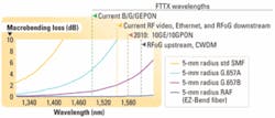
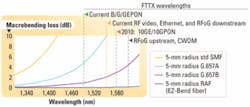
As Fig. 1 shows, current FTTH applications such as GPON use longer wavelengths that suffer much greater bending loss, potentially reducing reach and/or service reliability with these PON applications in which power budgets are constrained. New PON systems will use even longer wavelengths, with 2� to 4� the bending loss of today's applications.Commercially available G.657A bend-capable SMFs are optimized for most current and emerging bend-challenged applications in the central office, outside plant cabinets, and building backbones. However, the fast-emerging need to run optical drop cables to indoor optical networking units (ONUs) requires a new generation of ultra-bend-insensitive fibers. These applications require fiber and cable to allow tight 5-mm fiber bend radii to enable easy, copper-like optical drop-cable installations in multiple dwelling units (MDUs) and for in-home wiring (IHW). At 5-mm bend radii with one turn at 1,550 nm, traditional G.652D SMF can exhibit bending loss of 50 dB or greater, and even fibers meeting the new ITU G657A and G.657B specifications show unacceptable levels of 2 to 10 dB of bending loss under this condition.
Resonance Assisted Fiber (RAF) is a new ultra-bend-insensitive SMF that exhibits negligible added loss of only 0.1 dB maximum at 1,550 nm for one turn at 5-mm radius. The RAF is the first solid fiber that targets and meets the unique 5-mm bend-radius requirement of MDU and IHW drop applications while maintaining compatibility with conventional fibers. But before installing bend-capable fibers in any part of the network, the optical and mechanical performance under bending should be considered�to avoid breaking the rules for service reliability.
Traditional FTTH installations have used ONUs placed on the outside wall of the residence or building. Recently carriers and smaller providers have begun placing the ONU inside, to enable use of a lower-cost, non-hardened unit. For MDUs, ONUs are being placed inside each living unit to defer subscriber electronics investment and avoid the unpredictable costs of using existing metallic cables of varying age and quality. While conventional G.657A or B bend-capable fibers can support such indoor wiring applications using strict bend-radius control hardware or conduits, many carriers prefer using a fast, low-skill “copper-cable-like” installation process. Twisted-pair copper IHW is typically bent around sharp corners and stapled in ways that would increase bending loss of conventional fiber cables by 5 to 50 dB or more.Verizon recognized this challenge as it deployed fiber to the MDU and has published VZ.TPR.9424, “Verizon NEBS Compliance: Test Requirements for MDU Drop Cables,” which includes an “MDU Simulation Test” to simulate the uncontrolled optical drop cable bending possible in these installations. The PONs Verizon and other service providers deploy are constrained by optical loss; thus providers strive to minimize the optical loss of their access networks. As a result, the MDU Simulation Test subjects the optical cable to the all of following conditions simultaneously, with a maximum of only 0.4 dB of incremental bending loss permitted at 1,550 nm:
- ten 90° corner bends unloaded
- one 90° corner bend with 2 kg (4.4 lb) tensile load around the corner
- one 90° corner bend with 14 kg (30 lb) tensile load around the corner
- two 10-mm mandrel wraps
- thirty T25 rounded cable staples
Most bend-challenged applications are well served by suitable existing bend-capable fibers. The ITU-T-G.657 recommendation describes bend-capable SMF and includes “A” and “B” class specifications. The G.657A specification describes an SMF with about 3Ã� to 5Ã� lower bending loss than exhibited by standard G.652D fiber but is otherwise fully compliant with the G.652D recommendation. There are G.657A fiber products available with up to 10Ã� lower bending loss than seen with standard G.652D fiber. These G.657A fibers are optimized for central offices, data centers, riser cables, cabinets, most premises cabling, and even some outside plant cables that may experience tight fiber bending in terminals and the like.
Service providers worldwide began migrating to G.657A fibers for these applications in 2006 and 2007. G.657A fibers have also found some uses in FTTH applications. For example, some service providers have used G.657A fiber cordage in micro-conduits as a cost-effective approach in some greenfield indoor drop-cabling installations.Recently, some service providers began running optical drop cabling inside existing residences but reported unacceptable bending losses. The G.657B specification for bend-capable fibers was intended to target indoor installations, with bending loss up to 20� lower than G.652D fiber and no requirement for full compliance with G.652D.
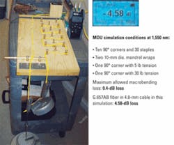
Recent testing of a 4.8-mm cable containing fiber compliant with G.657B found that this cable exhibited 4.6 dB of bending loss when subjected to the VZ.TPR.9424 MDU Simulation Test. This G.657B-compliant fiber exhibited 3� better bending loss than specified for ITU-G.657B fiber, yet produced more than 10� the 0.4-dB maximum bending loss specified for the Verizon MDU simulation, as shown in Fig. 2.
The United States Advisory Committee to the ITU and IEC standards organizations has recognized that the current G.657B specification for a 7.5-mm minimum bend radius fiber is grossly inadequate for optical fibers used in indoor drop applications. The committee, supported by leading carriers, has recommended to ITU Study Group 6 that a new indoor optical drop fiber specification be adopted. Study Group 6 is thus considering creating such a specification targeting a minimum bend radius of 5 mm, which would enable a rugged cable design installable using low-skill, copper-like procedures, including multiple sharp bends and stapling.
Service providers want fibers that feature much lower bending loss than allowed for G.657B fibers, yet remain compatible with standard G.652D SMF and FTTH equipment, including future transmission wavelengths and systems. Unfortunately, existing “beyond class B” fibers, including some claimed to be G652D compliant, exhibit one or more of the following limitations:
- Excessive bending loss (>0.1 dB/turn) in 5-mm radius bends.
- High splice loss to existing G.652 fibers.
- Specialized connector-mounting processes to fill holes.
- Specialized fusion splicing recipes.
- Excessive multipath interference (MPI).
- Incompatibility with widely used core alignment fusion splicing.
The RAF provides up to 500� lower bending loss than standard G.652 SMFs while meeting Verizon's MPI requirements and the 1,260-nm maximum cable cutoff as specified by the IEC, and offering an 8.8-µm mode field diameter compatible with splicing and connectorization. In addition, RAF fiber and cables are manufactured using existing high-volume manufacturing processes.
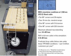
Drop cables using RAF are designed to be stapled and routed around corners with near-zero signal loss. These cables typically exhibit <0.2 dB of bending loss when subjected to the Verizon TPR 9424 MDU simulation, as shown in Fig. 3.
RAF is designed for simple, efficient deployment in installed or new networks. The RAF design enables termination and installation with standard tools and practices. As it is constructed of solid glass, it eliminates any concerns and limitations associated with the random holes existing in nano-structured designs. The consistent, solid structure of RAF assures uniform optical properties along the length of the fiber.
The RAF supports both clad and core alignment fusion splicing to standard G.652D, G.657A, and G.657AB fibers using existing equipment and procedures. Standard connector mounting, polishing, and cleaning procedures may be used, and RAF drop cables support both factory-terminated and fieldinstalled connectors. Field termination of RAF using new fusion splice-on connector technology eliminates the need for splice and slack management hardware, while mechanical splicing of RAF is also possible without concerns for index matching gel migrating into the holes that exist in some other designs. In summary, RAF can be terminated with the same processes used for conventional G.652D fibers.
The first RAF was developed to support a very high-powered laser application. The new RAF design was optimized for FTTX applications (see “Bend Insensitive Fiber for FTTX Applications” by Fini, et al., OFC 2009). As evidenced by the example simulation results in Fig. 4, the RAF design offers about 5Ã� to 10Ã� lower bending loss than trench-assisted fiber at the 5-mm radius.
The waveguide design of RAF consists of a ring and a trench around the core of the fiber. The trench helps confine the fundamental mode, while the ring helps attenuate unwanted higher-order modes, thus producing an optical fiber that has excellent bending performance while maintaining mode field and cutoff compatible with FTTX applications. The resulting design freedom enables RAF to offer optimized performance in the three key parameters: <0.1 dB/turn bending loss, ease of handling (splicing and connectorization), and G.652D compatibility.
While optical performance is critical, mechanical reliability is also essential to providing reliable service to customers. The 4.8-mm-diameter RAF drop cables provide protection for the fiber during installation and use, and are predicted to achieve <0.5 ppm/yr mechanical failure rates per cable in the severe Verizon MDU drop-cable simulation test. The 3-mm diameter RAF cables are optimized for installations behind molding, or similar protected environments, where bend radius management is undesirable. Weather-resistant indoor/outdoor 4.8-mm RAF cables are used if access to units is from outside, enabling elimination of connections and fiber management between outdoor and indoor cabling and allowing use of lower-cost indoor ONUs.
Compare the 25-mm minimum recommended bend radius of Category 5 and 6 cables, and the 60-mm recommended bend radius of RG59 coaxial cables, and it is apparent that RAF cables routable with a 5-mm bend radius actually offer far faster, more concealable installation than the “higher bandwidth” forms of copper. The net result is the RAF drop cables help enable installation up to 6Ã� faster than conventional bend-managed cablesâ��with a commensurate potential reduction in labor expenseâ��for cost-effective in-residence connections to the nearly unlimited bandwidth potential of optical fiber.
A triple squeeze of bend-sensitive longer wavelengths, tighter bend radii, and tighter power budgets has driven the deployment of bend-capable fibers in FTTX applications. While most bend-challenged installations can be optimally served with G.657A fibers, indoor optical drop cables installed using fast and easy traditional “copper service wire” procedures have been shown to require fibers with far beyond G.657B performance.
New ultra-bend-insensitive RAF indoor drop cables enable fast and easy installation using stapling and sharp corner bends, without the use of expensive, space-consuming conduits, and bend radius management. These RAF cables can bend without breaking the rules to enable both mechanical and optical performance reliability while preserving backward compatibility to conventional SMF and termination practices.
John George is director, systems and applications engineering; David Mazzarese is global manager for optical fiber technical marketing; and Pete Weimann is senior R&D engineer at OFS (www.ofsoptics.com).
Lightwave: Bend-Capable Fiber Variations Target Application Needs
http://lw.pennnet.com/display_article/339718/13/ARTCL/none/none/1/Bend-capable-fiber-variations-target-application-needs/
Lightwave: Video-Optimized Fiber is All about the Bends
http://lw.pennnet.com/display_article/298024/13/ARTCL/none/none/1/Video-optimized-fiber-is-all-about-the-bends/
Lightwave Online: FTTH Council: 4.4 Million Homes Connected with FTTH in North America
http://lw.pennnet.com/Articles/Article_Display.cfm?Section=ARTCL&SubSection=Display&PUBLICATION_ID=13&ARTICLE_ID=358636


