Installing a fiber-optic network: lessons from Germany
Test and installation remains on schedule despite the many complexities and challenges.
NIGEL SMITH, Bechtel Telecommunications
Which is easier: developing optical transmission equipment that operates at hundreds of gigabits, or putting cables in the ground that support this technology? As a construction and testing engineer, I've learned that the complexity of putting cables in the ground can match the challenges of deploying optical fiber. Some key lessons from the field are illustrated here by my recent experiences constructing a complex fiber-optic network connecting major German cities.
Work began on the German Network Development project in January 1999. The project scope was straightforward: Install a multiconduit, multicable fiber network around Germany connecting the major cities, including Hamburg in the north, Munich in the south, Frankfurt in the west, and Berlin in the east. Further, we were to construct 14 points of presence, 63 amplifier stations, and six regenerator stations.
Securing of all the rights of way needed to construct along the route was a complex task. Under the German Telecommunications Act (Telekom municationsgesetz-TKG), we were able to secure permission to build alongside the Autobahn highway system. The Autobahn system is regionalized, however, and the network route traversed 15 different regions, all with differing requirements. One authority required us to survey all its services prior to construction, while another insisted that we provide additional conduit for its use. Yet another required us to bear all costs in processing our application. Each of these individual requirements had to be tracked and reviewed legally to ensure compliance.
To complicate matters further, the requirements of 52 individual environmental impact assessment studies often conflicted with the Autobahn requirements, bringing negotiation and creative skills into play. When the route needed to cross the Rhine River, the Autobahn authority would not allow the use of the highway bridge because of planned renovation work. The environmental authorities would not allow us to go under the river because the banks were nature reserves. This conflict was resolved by providing additional capacity under the river for future crossings by other projects, thereby minimizing the long-term environmental impacts.
Private landowner issues were a special challenge on this project, because about 11,500 landowners were involved. Routine issues included family disputes, bankruptcy, change of ownership, and absentee-and in some cases, dead-landowners. We also faced thorny issues involving huge tracts of former East German land that were at the center of state versus private ownership disputes.
Those and many other issues had to be solved for every single kilometer of our 2,400-km route. It wasn't a task to be taken lightly. It's important to make sure that management systems can cope with the quantity, variety, and dynamic of the permits that need to be managed.
Information contained in the permits had to be translated into a series of route drawings. That meant we had to produce more than 2,900 individual drawings, each describing a section of route. These drawings ranged from 250 m within a city to 10 km or more along a rural path.
More than 120 people worked for six months to prepare the route drawings. One of the biggest challenges was the unavailability of consistent map data. Because East and West Germany work from different map bases and each region and city maintains its own maps, we had to secure, analyze, and often digitize maps from a number of sources.
The construction specifications complemented the route drawings. Each of the 14 construction specifications dealt with an individual element of the work, allowing us to be sure that interfaces between work packages were accurately and consistently defined.
It's critical to ensure construction specifications contain only the parameters you are prepared to measure against. That is the essence of a good specification-determining what is important to you and your client and focusing on those areas within the specification.
To meet our deadline, every week we needed to install 60 km of conduit, 8 km of which was made up of 102 horizontal directional drills, 23 chambers, and two repeater or regenerator sites. This pace continued for 39 weeks. The statistics shown in the Table on page 76 give a good indication of the magnitude of the project.
Successful construction on this scale depends on accurate progress information. Our job site was the size of a country, and more than 100 work locations within that site could be in operation at a time. It was essential that information be updated day by day, or even hour by hour. It's critical to use electronic systems to manage progress tracking. But the crucial ingredient is resources. There's no getting around the need for people on the ground-to monitor, inspect, solve problems, and report progress. At the height of the project, more than 900 people were deployed.
The language barrier sometimes led to surprising results. The majority of our field personnel were either German nationals or German speaking; however, the contract correspondence was in English. Shortly into the process of clearing land prior to conduit installation, we received a fax from our subcontractor: "We have found a copse," the fax read. "Please advise what we are to do." Further investigation revealed that the subcontractor had actually found a corpse. Indeed, two dead bodies were found during the project, in addition to numerous unexploded bombs.
By September 2000, the first of the 72 cable spans had been spliced and were ready for test. The optical fiber that we were deploying was ITU-G655-compliant nonzero dispersion-shifted fiber (NZDSF), with each of the two cables containing 72 strands.
In addition to duct tests (pressure and mandrel) and chamber inspections, test criteria for the cable included:
- Single-direction optical time-domain reflectometer (OTDR) of the cable on the drum to confirm compliance with the manufacturer's specification.
- Two-direction OTDR of every spliced cable link to confirm the optical length, overall loss coefficient, and connector quality.
- Two-direction calculation of every splice loss to confirm compliance with specifications.
- Two-direction insertion-loss measurement using a light source and power meter to determine accurate link loss for comparison with the loss budget.
Two-direction splice-loss calculations are necessary to determine an accurate value for splice loss, particularly when using NZDSF. The small core diameter of NZDSF compared to standard singlemode fiber causes slight geometry mismatches to affect the OTDR's interpretation of splice loss. That shows up on the OTDR as a "gainer" or negative loss at the splice point when measured in one direction. Clearly, negative losses are impossible in practice. Two-direction measurement and averaging the results cancels out effects caused by geometry mismatches.
Negative losses can be used to analyze traces. Once all the splices have been analyzed, the results sometimes show a series of overall negative losses. That is a good indicator that fibers have been crossed somewhere on the link. If there are enough of these overall gainers, it is sometimes possible to determine where on the link the fibers are crossed.
Testing optical fiber links is about establishing a process and following that process to the letter. The importance of this process was demonstrated on a single cable on this project.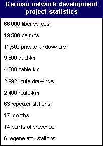
The longest individual cable link on the German project was 105 km between Frankfurt and Mannheim. To measure a fiber this length in one direction using OTDR can take three minutes. Allowing 20 seconds between fibers and testing a 72-fiber cable constitutes a test time of about four hours. Both ends of the link need to be tested, and time is required to travel from one end of the link to the other. The test results must then be evaluated to calculate splice loss. One test cycle can take one and a half to two days.
The first OTDR test is usually done to determine the location of the out-of-specification splices. If the test reveals crossed fibers, the fibers can be fixed, but the original test results are then useless. So the cable is tested again. The results produce a list of high splices, which the splicer must fix. The OTDR operator, meanwhile, is required on another job. The splicer works alone. Once the splices are fixed, the OTDR operator returns to measure again, which takes another day and a half. This time, although all the splices are good, the splicer has trapped a fiber in one of the closures, resulting in a macrobend. Macrobends are easy to fix, but because the closure has been opened, all the fibers must be verified again. The testing, fixing, and retesting may have to be repeated many times.
There is one process for optical fiber link testing. If you miss a step you might as well start over. The process includes:
- Verifying each fiber's continuity to ensure there are no macrobends or broken fibers on the link. That can be done fairly quickly using an OTDR, but it requires a person at each end of the link. If there are problems, they are fixed and this step is repeated.
- Using the initial two-direction OTDR to obtain the best results possible.
- Analyzing the results and preparing the rework list.
- Systematically working through the rework list. Verify each splice as soon as it is made, in at least one direction. After each splice closure is finished, recheck all the fibers for continuity, macrobends, and broken fibers.
- When all the reworking is done, undertake the final two-direction OTDR, followed by the two-direction insertion-loss measurement.
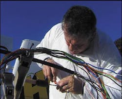
In all, the construction team made more than 66,000 individual splices in more than 900 splice closures. We achieved the specified splice loss in every case. The first splice was made in September 1999 and the last in May 2000 (see Photo); this process took a total of 38 weeks. We sourced splice crews from Germany, Italy, France, and the U.K. to meet the schedule and completion deadline.
The test/accept documentation for the fiber links alone amounted to 57 boxes of files. The only way to track this amount of documentation was to develop a database. Our testing database tracked more than 8,000 individual test sheets for completeness and acceptability and aligned all the punch list items to those specific test sheets.
Lessons from the trenches
The key lessons learned from projects like this are:
- Establish complete systems early.
- Fixing something that is broken onsite is harder than fixing it in the design office. The best solution, of course, is to design so that it doesn't break in the first place.
- Ensure that you can find the resources needed for the project quickly. That means being able to mobilize 900 people if the project demands it.
- The schedule is everything.
Finally, which is easier: developing next-generation equipment or installing the cable that will support it? Neither is easy. Technology development and installation both offer significant challenges. Each requires unique skill sets and approaches to allow successful integration. Even at its simplest, deployment is challenging, indeed.
Nigel Smith is a project engineer at Bechtel Telecommunications (Manchester, UK).
An expanded version of this article can be found on Lightwave's home page at www.light-wave.com.

