Interconnect technologies reduce maintenance costs
by Patty Tharavej
While the superior bandwidth potential offered by fiber-optic technologies is indisputable, fiber exhibits some shortcomings relative to copper-based networks in terms of simplicity and ease-of-use. Some key practical issues include 1) the susceptibility of fiber-optic connectors to polished surface damage (PSD) arising from contamination, 2) the fragility of fiber-optic cable to crushing and cracking, and 3) inadequate techniques to identify and trace fiber-optic cables throughout a facility.These issues are presently circumvented by following diligent cable management and maintenance procedures. However, technologies that make fiber-optic cable more “copper-like” from an operational perspective will likely play a key role in advancing the spread of optical fiber. These advances include fiber-optic cable cassettes, protective union adapters, and tone traceable fiber-optic cables.
Fiber-optic retractable cable cassettes offer a unique ability to manage excess cable lengths neatly and with minimal effort. These retractable patch cords provide a variable length of cable from a take-up spool within the cassette. The retractable end transitions continuously to a fixed length of cable attached to the cassette housing. Cassettes can be wall mounted, integrated into transmission systems, or rack mounted. The direct consequence of this cable management approach is enhanced network reliability.
Cassettes may incorporate simplex, duplex, ribbon, or plastic optical fiber. Since glass and plastic optical fibers exposed to sharp bends exhibit increased optical insertion loss, stress birefringence, and ultimately failure, the optical path within the cassette must follow a graceful series of bends to ensure high optical performance identical to standard patch cords. The cassette should maintain the bend radius of the jacketed cable above 1.5 inches at all times.
In most situations, one end of the cable and the cassette are attached to a fixed point, such as a fiber patch panel, wall outlet, or measurement instrument. The other cable end is pulled from the cassette and retained at the desired length. Of course, the cable also may be withdrawn back into the cassette.
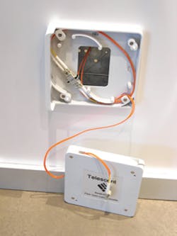
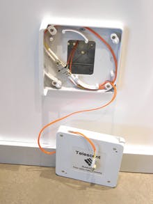
In a fiber-to-the-desk application, the cassette may be wall mounted by snapping into a wall mount mini-enclosure (see Photo 1). The mini-enclosure includes an internal fiber racetrack with retaining tabs for storing excess lengths of drop cable and accommodates an SC duplex or LC quad union adapter that interfaces the drop fiber to the fixed cable end of the cassette.
Wiring closets serve as the physical hubs of the network. Significant numbers of drop cables may converge to this location and interface with network transmission equipment using patch panels incorporating a large number of fiber-optic bulkhead union adapters. The polished connectors in the wiring closet-generally not the cleanest environment-must be diligently cleaned before connector remating. Polished connector endfaces are known to be the Achilles’ heel of fiber-optic cables. While it is preferable to leave fiber cables undisturbed once the system is installed, in practice the need to reconfigure the cabling arises during upgrades, enhancements, and troubleshooting. Typical connectors are rated for 500 mating cycles, but in the office or industrial environment connector lifetime can be reduced significantly due to PSD.In most situations, a costly service call is required to repair damaged connectors because skilled in-house fiber-optic technicians with specialized fiber-optic termination equipment are rarely available. Moreover, the network connection and often the equipment attached to it aren’t functional until the repair is complete.
Standard union adapters offer no protection if a contaminated or damaged fiber-optic cable is attached to another cable with an endface in pristine condition. It is common for connectors to propagate damage to other connectors. The resulting PSD leads to increased insertion loss and reduced return loss (RL), both of which can seriously compromise the network’s performance. For a damaged UPC polished endface, the RL can decrease from >50 dB to <30 dB.
The cost and time to repair damaged terminations is significant for fiber-optic cabling installed within a customer’s facility. For instance, damage to connectorized, behind-the-wall drop cables requires onsite repair by an experienced technician. Restricted access to damaged connectors within a populated, high-density fiber patch panel makes repair difficult, time consuming, and costly.
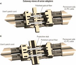
Although field-replaceable, quick termination connectors offer relief by eliminating the need for onsite polishing, they do require specialized tools and training to prepare the fiber-optic connector. In light of this, new adapter technology has been introduced to eliminate or at least dramatically reduce the need for onsite retermination. This adapter technology incorporates an internal, polished section of optical fiber, or “stub,” which serves as a protective barrier between two connector endfaces. This union adapter is plug-and-play compatible with standard union adapters, the only difference being the 3- to 4-mm increase in housing length to accommodate the internal stub.Figure 1 illustrates the differences between the standard union adapters and protective union adapters. The top figure illustrates an LC duplex-style industry-standard adapter, which produces direct physical contact between the user’s patch cord and the permanent side cable. In many situations the user’s patch cord may be exposed to contamination such as dust, and the condition of its polished fiber endface may not be known. There is a risk that the insertion of this patch cord into the union adapter will result in the transfer of damage from the patch cord to the permanent side cable. The only solution to remediate such damage would be to replace the permanent side connector.
Alternatively, the bottom of Fig. 1 illustrates a protective union. In this case, damage from the user’s patch cord would affect one or both protective stubs rather than the permanent side LC-PC cable. The stubs serve as physical barriers isolating the spread of damage to the protective union rather than the permanent side cable. Repair involves the simple, low-cost replacement of the disposable protective union. This process can be performed onsite with no training or special tools and with minimal effort.
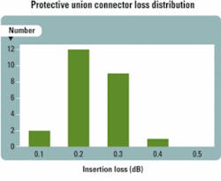
Protective union achieves low-loss interconnection nearly identical to standard unions by utilizing stubs with high concentricity. Figure 2 plots the excess insertion loss distribution measured at 1,310 nm for a random sample of 25 multimode 62.5-µm protective unions with typical concentricity errors of <3 µm. This distribution displays a maximum loss of 0.4 dB and an average loss of 0.25 dB. Similar high performance is achieved for singlemode protective unions utilizing stubs with sub-micron concentricity, exhibiting a typical insertion loss of <0.15 dB and RL >50 dB.
While protective unions have clear application to behind-the-wall connectors, an area where they can play a particularly significant role is in patch panels. Large numbers of densely populated union adapters are common in fiber-optic patch panels and crossconnects. Within the enclosure, a trunk cable with, say, 144 individual fibers is separated into individual strands, each terminated in a polished connector. Typically, short preterminated connector pigtails are fusion spliced to the trunk cable. The connectors fanning out from the trunk cable are attached to the back receptacles of bulkhead unions. Fusion splices and excess cable lengths behind the face plates are organized on splice trays and spools within the patch panel enclosure. Connectorized fiber distribution cables are then attached to the front receptacles of the patch panel.
Should one of the distribution cables become damaged, it is easily accessible and can be quickly replaced. However, if a damaged or contaminated cable is attached to one or more union adapters in the patch panel, the connectors embedded in the patch panel enclosure may become damaged. Typically, much like the behind-the-wall terminations, these connectors and their cables are difficult to access for repairs.These situations can be remedied by populating the patch panel with plug-and-play compatible protective unions, which are drop-in replacements for standard unions and eliminate the spread of damage to backside connectors. In this way, the protective unions isolate the damage and are quickly replaced, leaving the permanent side connectors within the patch panel in pristine condition.
As fiber-optic cable use becomes more prevalent in enterprise networks, it becomes important to have a fast and convenient method of tracing the location of a cable from the patch panel to the user’s connection. To address this need, electric tone traceable fiber-optic cable has been developed.
This building block uses duplex fiber-optic cables incorporating multimode, singlemode, or plastic optical fiber. One such design features a microscopic electrical conductor on the outer surface of the cable jacket. The conductor is located at the bridge in the PVC jacket joining the two separate fiber-optic elements. It is important that the conductor lies on the outside of the jacket, because this design allows even connectorized cables to be traced without having to remove the connectors to gain access to an internal conductor.
The cable structure is physically identical to standard duplex cable, utilizing the traditional aramid fiber strength member and tight-buffered fiber. By recessing the conductor, it does not come in contact with surrounding cables in a cable raceway, even if the cable jackets touch one another. This ensures that the tracing signal only travels along the cable under test and prevents unwanted short-circuiting of the voltage tone.
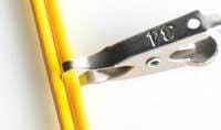
Standard electronic tone generators provide a 5- to 10-V RF tracing signal with 1- to 10-kHz frequency. The electromagnetic emission is detected by a handheld tone detector. The tone is launched down the cable simply by attaching the tone generator’s clip to the bridge region of the duplex cable jacket (Photo 2), thereby “tagging” the cable with a unique electrical signature.
The incorporation of an outer conductive wire on the cable jacket eliminates the need to cut or strip the cable to gain midspan access to inner wires within the jacket. This “noninvasive” feature is particularly important for fiber-optic cables whose strength may be seriously compromised if the jacket is cut midspan. The tone generator can be attached to the cable at any location and there is no need to cut off and replace costly fiber-optic connectors simply to gain access to the electrical conductors.
Fiber-optic cabling and interconnects offer the potential for practically unlimited bandwidth far superior to the performance of copper and wireless systems. However, this performance comes at the expense of ease of use.
Innovations in fiber-optic interconnect products should strive to mimic the ease of use and simplicity standards set by present-day copper cabling products. Examples of this innovation include cable cassettes, protective union adapters, and electrically tone traceable cables. The need to reduce the fiber-optic network’s maintenance cost and downtime will continue to drive further advances by enterprise networking equipment suppliers and increase the value proposition of fiber-optic technology.Patty Tharavej is the director of marketing at Telescent (www.telescent.com).
