Connectorization choices can save FTTP costs
Making early cost-sensitive decisions when deploying fiber to the premises (FTTP) is often a difficult yet necessary consideration in today’s competitive access environment. Service providers not only must consider initial installation costs, but also peer into the future in terms of the operational and maintenance expenses that follow service turn-up. Extensive cost modeling provides compelling evidence that during the planning and implementation stages choosing the correct method of joining different segments of the FTTP network-more specifically, when to use hardened connectors versus field splicing-will provide significant financial benefits throughout the life of the network.
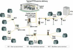
Although FTTP architectures may differ in design, they share many basic similarities. One common factor is cost models show that a reduction in the number of splices, splice technicians, and splice-crew deployments decreases overall network costs significantly. Additionally, a new architecture that introduces centralized splicing locations and pre-terminated drop terminals known as multifiber service terminals (MSTs) can further reduce initial deployment expenses (see Figure). Finally, the use of connectors in two basic areas of the FTTP network-the interface between feeder and distribution plant and the interface between distribution and drop cable portions of the outside plant (OSP)-will enable easier and less costly access when technicians perform maintenance, troubleshooting, and service turn-up operations.
Early FTTP-network architects spliced every juncture of the network, from the central office (CO) to the subscriber. This mindset was based on initial concerns over cost and the reliability of connectors in the OSP environment. For example, as outside temperatures approached -40°F, the thermoplastic used in the connectors tended to shrink more than the optical fiber, causing microbends or bunching of fiber that would result in insertion loss.
In recent years, connector and cable assembly reliability has improved greatly. Studies have proven that new cables and assemblies can operate in the most austere environments. Components are manufactured with low-shrink plastic, and potential open-space areas are filled with void-free adhesives. Today’s components are factory-designed to compensate for temperature changes and meet the requirements of the Telcordia GR-326 sue 3 standard.
Fully armed with the latest connectors and cable assemblies specifically designed for OSP performance, network architects now have connection options. Rather than splice the entire network together, they can now place connectors at points in the network where they make the most sense.
So where in the network does it make the most sense to use connectors? Connector interface points have long been standard in the CO to simplify troubleshooting, reconfiguration, and service turn-up. The same holds true for today’s FTTP architectures-proper placement of connectors at key junctions in the OSP provides superior flexibility in the network. It simply makes more practical sense to choose connectorization over splicing wherever these cost-saving benefits can be achieved.
The typical elements of the optical distribution network segment of an FTTP architecture consists of feeder cables routing to a fiber distribution terminal (FDT) where optical splitters are housed. From the FDT, a distribution cable will route to the multifiber service terminal (MST) where the drop cables tie in. From the MST, drop cables are routed to the optical-network terminals (ONTs) at each subscriber premise.
Throughout this portion of the network, there will be many locations where fibers must be physically joined together. At many of the optical junctions such as along the feeder and distribution cable runs fibers will simply be spliced together. There are, however, certain critical junctures at the FDT, MST, and ONT where the use of optical connectors will provide much better flexibility in the operation of the network.A connector pair is always a better choice at any point in the network where technicians will require regular access for testing, turn-up, and service reconfiguration. At these locations, a connector interface provides significant operational cost and time savings advantages over fusion splicing. Test access should always be the first consideration for replacing a splice with connectors.
Fault isolation in an FTTP network presents at least two key challenges for technicians. First, OTDR traces are difficult to decipher from the CO once the trace hits the splitter in the FDT. Therefore, the technician must tap into the network at the FDT. If all the connections at the FDT are spliced, a splice technician is required at that location to break into the appropriate splice between the splitter and distribution cable. Once the trace is completed, the splitter must be re-spliced to the distribution fiber. This process is time-consuming and expensive-and puts the network at risk for further problems that could result from handling the fiber.
A connector interface at the same splitter output offers easy test access to all the distribution cables. Test access then becomes a simpler matter of locating the suspect distribution fiber on a bulkhead, disconnecting the splitter output pigtail from that port, and plugging in the OTDR launch cable. Once the trace is completed, the launch cable is disconnected from the distribution port and the splitter output pigtail is reconnected. No fibers are broken and no splicing is required. Also, since all splitter output fibers are connected to a bulkhead, they are protected with a jacketing that prevents damage during normal handling.Additionally, the FDT is one point where network design significantly impacts how quickly a problem can be isolated. Testing from the customer’s ONT may not be easily accomplished for many reasons such as its location or customer schedules. But using the splitter output as a centralized demarcation box provides a single location with test access to any fiber for multiple homes. Again, using connectors in place of splices at each splitter output makes the process easier and much less costly.
Another location where connectors can provide significant savings is at the MST. A hardened-connector approach at the MST reduces cost and requires far fewer splice-technician deployments. That’s a relatively new architecture incorporating pre-terminated MSTs with up to 12 fibers each-extended from a centralized splice location to each MST. This architecture eliminates running very large cables and accessing those cables at numerous locations.
Even though the number of splices is about the same, all splices are done at a single location, further reducing the overall costs of splicing within the FTTP network. Since much of the splice costs are generated during setup, a central splice point enables the technician to set up one time and splice as many as 12 smaller cables onto the distribution cable.
Additionally, no splice cases are required at the MST, making the hand holes or pedestals that store the service terminals much smaller. That’s an added benefit, both from a material and installation standpoint. Since many municipalities prefer smaller, less obtrusive pedestals or smaller hand holes, the use of MSTs makes sense when planning the network’s architecture.
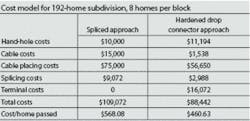
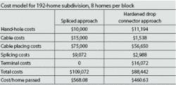
Cost modeling indicates an FTTP network that incorporates MST hardened-connector technology decreases cable costs by more than 85% over a traditional architecture in a 192-home subdivision (see Table). That’s primarily due to the cable now being included in the terminal costs. The cost of pulling fiber in the same scenario decreases by about 25% and splicing costs decrease by about 70%. In fact, even though the MST approach adds more costs for service terminals, the overall cost is significantly lower for the distribution portion of the network-about 19% less per home passed.
At the drop cable portion of the network-between the service terminals and ONTs-a hardened drop connector approach reaps more cost advantages. Factory-pre-connectorized drop cables are available for connecting the service terminal to each subscriber. These cables are pre-connectorized at each end and cut to specific lengths to greatly reduce the cost of drop cable installations in terms of time and skill level required. Cost models indicate the overall cost of using factory-connectorized drop cables in place of spliced bulk drop cable was at least 25% less.
Despite the arguments that connectorized approaches result in more optical loss and also require more inventory and slack storage provisions, the same conclusion is consistently reached by comparing cost models: The hardened drop connector approach incurs lower overall installed costs to the FTTP network. The choice of using splices or hardened connectors at various points of any FTTP architecture boils down to a cost decision for network architects. Making the correct choice saves time, money, and frustration during both network deployment and operation. It’s never a question of a spliced network over a connectorized network. Rather, superior long-term network performance, reliability, and flexibility are achievable for the network that uses both connectors and splices wherever and whenever they make the most sense.Trevor Smith is product manager for ADC’s Fiber Cable Management Connectivity Business Unit (Minneapolis, www.adc.com).


