Vendors tout fusion splicing to the home
Fusion splicing is a relatively mature technology, having been widely used for the past 20 years. But while the basic technology has not changed, its complementary features have evolved to make fusion splicing simpler, faster, and more cost-efficient. That is especially critical in fiber to the premises (FTTP) applications, where cost is an issue and technicians may not be fiber savvy.
At its most basic level, the fusion splicer performs two functions: It precisely aligns the core of two optical fibers, then fuses those fibers together, forming one seamless length of fiber. Two electrodes in the fusion splicer generate a high voltage of electricity, known as an arc, which actually melts the fibers together. The temperature of the arc is typically between 1,600° and 1,700°C.
In the past, splicing has occurred in controlled environments, with network installers deploying specialized vans filled with the necessary equipment. But as fiber becomes more ubiquitous, fusion splicers must be smaller, lightweight, and portable.
“As fiber goes deeper into the network, it’s getting closer and closer to the individual building, the individual home-whatever is on the other end of the fiber,” reports Mark Boxer, engineering manager at AFL Telecommunications (Franklin, TN). “As a result, we’re seeing a trend toward splicing in some unorthodox places,” he says, including poles, manholes, and next to houses.
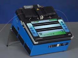
AFL’s recently released 50S fusion splicer, for example, features what the company claims is a unique wind protection design, enabling the user to successfully splice in cross winds up to 30 mph. “Anywhere one would expect to see fiber, ultimately, we have to be prepared to splice there,” says Boxer.
The challenge for fusion-splicer manufacturers has been developing equipment that is both smaller and higher-performing. In FTTH applications, for example, the optical performance of the fusion splicer is critical. The splitter is the key component in the PON architecture and results in a relatively high level of optical loss. “When you test a PON network, which has a splitter in it, if you try to test through the splitter, you don’t know where your signal is coming from,” explains Bernhard Deutsch, director of marketing development for Corning Cable Systems (Hickory, NC). “You can’t tell how big the loss is at a specific point after the splitter. So it is critical that you be able to estimate or determine the splice loss.”
Corning’s OptiSplice iLID, for example, functions much like an optical time-domain reflectometer (OTDR), enabling the user to measure the optical loss at a specific point on the fiber. “It is basically used for active alignment,” says Francois Barbeau, Corning Cable Systems’ product-line manager of splice and test equipment. “As the splice is being performed, the unit monitors the amount of light going from one fiber to the next. It will actually stop the fusion process when the maximum amount of light has gone from one to the next, then it uses this data to come up with a very precise measurement of the splice loss.”
The FTTH network itself can be divided into three segments: the feeder, distribution, and drop. Fusion splicing occurs primarily in the feeder and distribution segments, since many network installers now use pre-connectorized fiber in the drop to reduce the overall cost of the network.
The labor costs associated with fusion splicing are high, reports David Meis, marketing manager of FTTX technology at Corning Cable Systems. “Shifting over to pre-connectorized drops in the drop segment allows you to isolate and even tier your labor force, so you are optimizing how you deploy,” he explains. “Now I can have a service technician hooking up a home rather than a highly skilled and highly paid fusion splicer. Fusion splicing certainly is not going away. It’s just reallocated to the critical areas of the network, such as the feeder and distribution segments.”Manufacturers of fusion-splicing equipment also report an increase in the use of ribbon fiber for FTTP applications, which require mass fusion splicers. “This is a relatively new trend in the last half-year in the feeder and distribution sections,” says Deutsch. “This surprised us, quite frankly, because we thought it was just loose tube, single-fiber applications for FTTH, but we see at least 50% of it is ribbon.”
The speed of deployment and cost savings associated with ribbon fiber is increasing its popularity. “At a certain point in the network where you have many splices to accomplish at one point, say 288 or 432, it behooves the service provider to use a mass fusion splicer,” says Meis. “Imagine the savings that are realized when this operation is done with 12 fibers at once versus just one.”
According to Per Karlsson, sales and marketing manager of fusion splicers at Ericsson Network Technologies (Stockholm), ribbon fibers can only be spliced using a fixed V-groove mass fusion splicer, which enables the user to splice together more than one splice joint at the same time. Individual fibers inside the ribbon cable are placed in a channel or V-groove to ensure the precise alignment of each fiber. Six- and 12-fiber mass fusion splicers are the most common, and they are now as small as their single-fiber counterparts. “It doesn’t matter if we’re talking about FTTH or long-haul; ribbon can only be spliced with V-grooves,” adds Karlsson.
With the growth in the FTTP market, many technicians are moving from the copper to fiber world. “There will be people who have never touched a fiber now tasked with connecting the home with fiber,” muses Deutsch. As a result, fusion-splicing equipment must be less complicated and more intuitive.
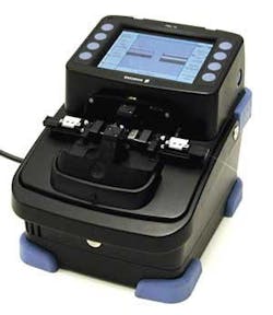
Today, splicing is “very easy,” says Karlsson. “You basically press a button and the machine does all the work. For example, we have our FSU 15 FI, which is our new-generation splicer. It’s very intuitive, very easy to use. Anyone who has ever used a computer will recognize the user interface.”
Even the best fusion-splicer manufacturers can’t take all the manual labor out of splicing, however. Each fiber must be prepared before it can be spliced, and that process still requires a technician. A fiber must be separated from the cable, stripped of its coating, and thoroughly cleaned. Then it must be cut or cleaved to a less than one-degree angle so that the ends of both fibers are square with each other.A number of features do make the technician’s job easier, including integrated cameras that allow the user to see both axes of the fiber, which aids in fiber alignment. Built-in alarms alert the user to dirty fiber or bad cleave angles. Fiber recognition features are typically included as well, enabling the splicer to detect the fiber type, whether it is singlemode, multimode, nonzero dispersion-shifted fiber, etc., and change its parameters accordingly.
The current generation of devices is also much faster, notes Boxer, which is important because labor accounts for a big portion of the overall cost of the FTTP network. “What we’re trying to do with every [generation of fusion splicers] is decrease the amount of time the entire operation takes,” he says.
The fastest machines on the market can perform a splice in roughly 9 or 10 sec, and they can heat-shrink a protective sleeve over the splice in about 30-35 sec, reducing the overall splice time to somewhere in the neighborhood of 40-45 sec. The previous generation, available two or three years ago, required 12-15 sec per splice, while the tube heat typically took over a minute.Meghan Fuller is the senior news editor at Lightwave.


