FTTH networks demand increased CO density
by Mark Turner
Fiber-optic interconnection hardware (FOH) in the telecommunications central office (CO) or cable-television video headend (HE) used to be relatively insignificant because the number of transport fiber ports in the CO or HE was fairly small. However, the optical access networks being built today require harmonious integration of the CO/HE FOH with the outside plant fiber cable and FOH. While DSL and hybrid fiber/coax networks can often operate with 24 to 48 fibers, FTTH networks—even where a local convergence point (LCP) splitter cabinet is used—often require hundreds or even thousands of fiber ports in the CO. We will see an example later to support this assertion.First, why has there been a dramatic shift from solely optical transport to complete optical access? Service providers need to be able to offer Internet access, digital television, and phone service (often referred to as the "triple play") to attract and retain broadband customers. Hybrid networks are usually limited by distance or the number of subscribers on a node. The fastest DSL network can generally only deliver the triple play to subscribers about half a mile from the multiplexing equipment. Bandwidth in hybrid networks is constrained by the number of homes on a single node and electrical noise impairments that can corrupt the waveform.
FTTH is the only all-optical access platform that can transparently scale to reliably deliver gigabit-per-second speeds throughout the serving area. This factor is truly the root cause of the transition to complete optical access. So, how should the optical access network be designed?
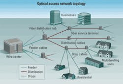
The best way to build a scalable FTTH network is by ensuring that the physical layer of the network can support various access architectures. This is usually best accomplished with a centralized architecture. This single-fiber approach to each subscriber�s home has been widely adopted due to its cost-effectiveness and versatility to support various architectures. PONs are commonplace today, and switched Ethernet or point-to-point networks may also be applicable in certain situations where existing Ethernet infrastructure is already in place. Figure 1 illustrates an FTTH network topology with three distinct fiber cable segments: feeder (blue line), distribution (red line), and drop (green line).
In an area that is being overbuilt with FTTH via a centralized architecture, each home or business would have a fiber (red line in Fig. 1) dedicated to it at a fiber service terminal. When the home or business subscribes, the fiber-optic service drop (green line in Fig. 1) can be quickly interconnected to the terminal. So, where does the upstream end of that fiber strand (red line) originate?Each subscriber�s fiber could originate at a neighborhood LCP cabinet or it could originate all the way back at the CO. Either origination point can scale well to support future bandwidth needs that will eclipse 100 Mbits/sec for each home. With that in mind, the total cost to deploy a fiber cable to support all the homes in the targeted area should be carefully considered.
Total cost includes both fiber cable cost and, most importantly, construction cost. Cable pathways, either overhead or in-ground, are often conducive to the use of ribbon fiber cables for maximum efficiency and least installed cost. The following FTTH deployment example illustrates the use of ribbon cable, high-density CO FOH, and LCP splitter cabinets to efficiently, cost-effectively, and reliably support thousands of homes in a fairly dense serving area.
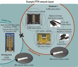
Figure 2 depicts a sample design for a city with about 3,450 homes per quadrant.
Beginning at the CO, a high-density frame can accommodate up to 1,728 fiber ports. Typically, network designers have selected the SC APC for FTTH networks due to its high-performance return loss of =65 dB.The feeder ring (blue line) can be a single, gel-free ribbon cable with 864 ITU G.652.D singlemode fiber strands. This ring can be looped around the city to provide a manual failover mechanism. In this example, one frame accommodates up to 864 operational ports with as many as 864 additional ports on standby (216 strands per quadrant). If the ring were to be cut, the patch cords for the affected quadrant(s) could be quickly connected to the other side of the frame via the patch cord take-up area in the center of the frame. Without a manual failover mechanism, the city ring would lose service until the cable cut was fixed, requiring costly and time-consuming field repairs on short notice.
It is important to note that the ribbon cable dramatically reduces the fiber termination time in the CO when the network is built. By mass fusion-splicing 12 fiber pairs at a time on the frame, it can take only about three man-days (assuming the typical 10 minutes per mass fusion-splice) versus about 14.5 man-days (assuming the typical 4 minutes per single fiber splice) to splice a fiber pair at a time.
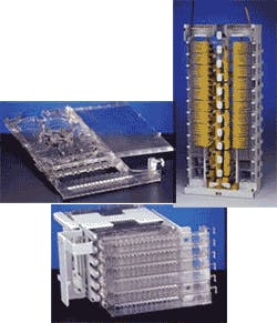
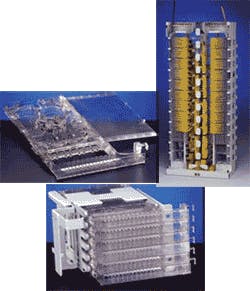
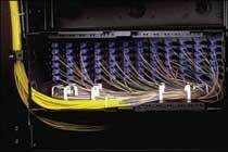
The photo on p. 1 shows a high-density frame and its components, including a 72-port module housing that can be added incrementally as needed. Each sliding drawer contains 12 fiber ports.
Inside the transparent drawer, a 12-strand ribbon pigtail can typically be fused to the 12-strand ribbon in the feeder cable in about 10 minutes. The clear plastic design enables the ends of a traceable patch cord to be located very quickly. Also, if the serving area size is relatively small and a centralized homerun layout is used instead of the LCP splitter cabinet discussed in this example, the module housing can accommodate three 32-port power-splitting modules. Additionally, WDM modules are often needed to combine the out-of-band video overlay signal onto the PON signals. The module drawer can also be used for this purpose when needed. On the frame itself, patch cord slack can be conveniently stored only in the center of the frame, so the excess patch cord length can be easily managed.
Referring back to the FTTH network layout example from Fig. 2, at each of the four crossconnect locations shown (indicated with an "X") 216 feeder-ring cable strands are mass fusion-spliced into four 144-port, prestubbed patch panel housings (see photo on p. 22).
There are also three additional 144-port prestubbed housings inside the crossconnect cabinet that are mass fusion-spliced to 216 strands inside the 864-strand distribution ring cable (red). Actually this cable serves as both a feeder and distribution cable. The first 216 fibers of this cable are dedicated for the feeder ports in the LCP cabinets with the remaining 576 used locally as distribution strands from each LCP cabinet. There can be a maximum of six LCP cabinets per distribution ring cable (red). Six cabinets per ring with 576 subscribers per cabinet provide subscriber capacity of 3,456 per quadrant ring. Four quadrants with service for 3,456 equal 13,824 subscribers in the serving area. All of these subscribers can be served from only 864 ports in one frame.The distribution ring cable also has a manual failover mechanism in case the cable is cut. The patch cords connected to the affected ports in the crossconnect cabinet could be reconnected into the other side of the quadrant ring as needed.
Each of the six LCP cabinets per quadrant has 18 upstream strands back to the CO to support a 1�32 PON split ratio. Thinking into the future, an additional 18 strands can be included for a 1�16 split ratio that provides significantly more subscriber bandwidth. In addition, these 36 strands enjoy manual failover support via the crossconnect cabinet patching and redundant feeder ports in the LCP cabinet.
As for the 576 distribution strands per LCP cabinet, if the distribution ring cable is cut, only a fraction of customers on a few cabinets may temporarily be without services until the distribution ring cable can be mass fusion-spliced back together.
A key benefit of the distribution and feeder ring cable is that one cable sheath can fit inside a single 1.25-in. duct or overhead messenger wire. Any side street along the quadrant ring can tap into the distribution cable with a ribbon terminal distribution system and mid-sheath access closure. Then, the 4- to 12-subscriber strands automatically appear at the prestubbed terminals with hardened ports that are ready to accept a preterminated service drop cable with a hardened plug
Today�s optical access networks demand harmonious integration of the CO FOH with the outside plant fiber cable and FOH for operational efficiency and cost-effective installation. With a centralized architecture, a high-density frame can leverage the benefits of gel-free ribbon fiber cable, as 12 strands can be mass fusion-spliced right inside the slide-out drawer without requiring additional splice housing space either on or off the frame. Without this space-saving design, some COs or remotes simply would not have enough room to accommodate all the strands required in the serving area.
Finally, having the right design enhances the operation of the FTTH network during exceptional circumstances and transparently enables future bandwidth upgrades or transmission equipment changes to occur.
Mark Turner is manager, consultant engineers, at Corning Cable Systems (www.corningcablesystems.com).
