Modeling and simulation improve FTTH planning
Planning an FTTH network can be complex, time-consuming, and error prone. Software tools make this job easier, both in terms of developing a business model and determining the right architecture to execute it.
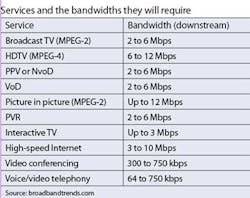
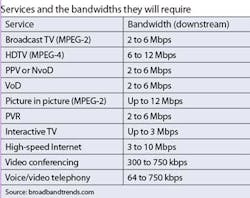
Fiber-based services are in high demand from businesses and consumers alike. Driven by a desire for services such as multiple high-definition televisions, broadband Internet access, two-way broadband connections, and interactive applications like multiplayer gaming, consumers are realizing that broadband DSL just does not provide the bandwidth and quality of service they need. Businesses driven by global competition and shifting business models also have a huge appetite for fiber-based services, and most vendors are estimating they want to deliver about 35 Mbps downstream and 10 Mbps upstream to accommodate the services shown in the table.
To meet this demand, keep pace with competition, and keep up with marketing commitments, carriers are investing enormous amounts of time and money in a race to roll out fiber as quickly as possible.
How to begin
A plethora of issues immediately jump to the forefront. First and foremost is how to effectively control the cost of the civil engineering aspects of the deployment, which can range anywhere from 60% to 80% of the total estimated network costs. To resolve this sticky issue, it is essential that fiber planning take on the “what, when, and where.” The planning process will need to determine the right architecture and the sequencing and location of the fiber and splitters to best optimize revenue versus costs and speed deployment.
To address the architecture issues for FTTP, planning must begin with acquiring topology information like demand points, physical conduit locations and capacities, and central office (CO) locations. This data will be used to examine and evaluate various architecture choices, using network modeling tools that form the basis of the architecture decision support system. FTTP implementations can be either homeruns or centralized or cascaded PON, meaning they can have either a single centralized splitter (see Fig. 1) or multiple, cascaded splitters (see Fig. 2). The latter is almost always limited to two splits.
Centralized PON architectures require fewer splitters, but more fiber, and have the following attributes:
- the splitters are located closer to or in the central office, usually with a 1√ó32 split for BPON/EPON and 1√ó64 for GPON
- subscribers share bandwidth from CO to splitter
- use less fiber (and lasers) than homerun and more fiber than distributed, but fewer cabinets
- CO port efficiency is higher when take rate is low
Cascaded or distributed PON architectures have two-tiered splitting architectures—1×8 splitting followed by a 1×4 split, for example. Thus each end user receives 1/32 (or 1/64) of the bandwidth. This architecture also has the following characteristics:
- uses fewer fibers but more splitter cabinets than centralized
- bandwidth efficiency can be low for low take rates
- discourages horizontal business model (less competition)
- most difficult to maintain and repair
The most effective way to evaluate these architecture tradeoffs and determine which will be optimal for a carrier's needs is to use a set of network and component modeling/simulation tools. These tools can then also be used for both architectural business decisions and technical component-level evaluations.
Making a choice
Let's take a look at the business side first. What are the key data points that a carrier needs in order to make effective architecture choices? The first items that need to be considered are the services, take-up rates, and revenues per service. As take-up rates are not 100% on day one, multiperiod planning will most accurately model this aspect; thus it is important to forecast take-up rates on a monthly, quarterly, or annual basis.
The next data points to consider are the physical locations of the endpoints, e.g., a single-family residence, multitenant dwelling, or enterprise. Finally, carriers need to evaluate the topology of the existing underground conduits or aerial paths that the fiber will traverse.
Once this data has been collected, it can be used to create mathematical models of the network topology and demands, as well as to run what-if analyses on the network, to determine optimal locations for splitters and optimal fiber paths. Using these same methods and tactics to conduct multiperiod forecasting can help optimize multiperiod roll-outs.
“To help optimize the large investment carriers are making globally to roll out new FTTX networks, carriers should invest in powerful network resource planning (NRP) solutions,” says Scott Bechtloff, global lead, network engineering and planning, Communications and High Tech practice, Accenture (www.accenture.com). “There are a large number of variables involved in planning out FTTX networks‚Äîsuch as topology selection, placement of network elements, and phasing of the roll-out to accelerate returns. An NRP solution helps enable carriers to analyze multiple scenarios much faster than can be performed manually.”
According to Bechtloff, these analyses help the business improve the accuracy of its business case. They also help network planners improve the selection of technologies and the location of network elements. When an NRP is integrated with a carrier's engineering design tools, the solution can provide even more value. Data accuracy is improved and design times are reduced.
Another benefit that an NRP tool can provide, Bechtloff says, is the ability to enforce standards across multiple planners. As a carrier rolls out its network over multiple geographies, the more standard it can make its deployment configurations, the easier it will be to maintain the network, increase reliability, drive down equipment costs, and reduce maintenance costs.
Tools decrease complexity
Developing an optimal design for fiber-based networks belongs to a class of nondeterministic polynomial complete problems, meaning that a solution can be verified fairly easily once you have one, but the generation of the solution cannot be executed in any reasonable time for real carrier-grade networks. The computational time for planning and solving these kinds of problems increases exponentially with the size of the network—rapidly approaching mega-years in CPU time. Therefore, it is necessary to use a set of heuristic algorithms, like those in an NRP tool, to find the best possible solution in a reasonable amount of time.
This is precisely why mathematical models are used. NRP tools provide the planner with a level of abstraction where they can think of the network in terms of elements that are common to their understanding. When combined with a Geospatial Information System (GIS), these modeling tools can also lend visual understanding to the planner. Meanwhile, the details of the complex heuristic mathematical algorithms are hidden from the planner and the task.
An NRP tool can also perform financial analysis to determine which architecture will deliver the best return on investment. These calculations will be based on the model's output in terms of different architecture approaches, as well as the “what, when, and where” of splitter equipment and what size fiber cables are required.
Beyond this level of planning lies the deeper optical/photonics design component of PON-based FTTP planning, which is typically done by vendors who produce the specifications for PON equipment. These vendors will also focus on transmission issues, such as sufficient optical signal-to-noise ratio and bit-error rate. For example, can 10-Gbps downstream and 2.5-Gbps upstream speeds be supported over the PON architecture at a range of 20 km? How will this perform at a 1,490-nm wavelength for downstream versus 1,310 nm for upstream? Is the signal affected by optical phenomena such as Rayleigh and Brillouin backscattering?
Optical transmission issues at the physical layer in a PON, like the type of modulation and optical carriers to be used, must be fine-tuned by the vendor in advance. This tactic will ensure optimal equipment performance, as well as a high quality of experience for consumers. Optical simulation tools provide equipment and system designers the ability to model such PON equipment and systems on a computer, simulate multiple iterations of the design while varying different combinations of parameters, and fine-tune them until they are ready for more extensive prototyping. These tools also reduce the time-to-market and cost for rolling out the new PON-related equipment and products that are essential to gaining market share.
The right tool for the job
Service providers realize that FTTH is the best choice for delivering the downstream bandwidth for triple-play services including multiple HDTVs and high-speed Internet and the upstream bandwidth subscribers want for the “networked lifestyle.” Planning fiber networks is an extremely complex human endeavor as well as time consuming and error prone.
Network resource planning for FTTH deployments can now be accomplished with the aid of sophisticated network modeling and simulation software. Such software reduces the complexity of FTTH planning and provides the planners with a range of business and financial analyses that enable them to deploy the most cost-effective fiber network in the shortest time.
Michael Devlin is vice president of business development at VPIsystems (www.vpisystems.com).
One-CLICK LINKS
LIGHTWAVE:How Invisible Should Your FTTH Network Be?
LIGHTWAVE ONLINE: Creating a Cost-Effective Plug-and-Play FTTP Architecture
LIGHTWAVE:Addressing Profitability Issues in FTTP Network Management


