Ethernet in the first mile
With trials and standards initiatives underway, Ethernet PON is poised to take on the local loop.
GERRY PESAVENTO and MARK KELSEY, Alloptic Inc.
Passive optical networks (PONs) address the last mile of the communications infrastructure between the service provider's central office, headend, or point of presence (PoP), and business or residential customer locations. In residential areas, the last mile, also known as the access network or local loop, consists predominantly of copper telephone wires or coaxial cable-TV cables. In metropolitan areas, where there is a high concentration of business customers, the access network often includes high-capacity SONET rings, optical T-3 (45-Mbit/sec), and copper-based T-1 (1.5-Mbit/sec) lines.
Typically, only large enterprises can afford to pay the $3,200 to $4,300 per month that it costs to lease a T3 or an OC-3 (155-Mbit/sec) SONET connection. The T1s at $375 per month are an option for some medium-sized enterprises, but most small businesses and residential customers are left with few choices beyond plain old telephone service (POTS) and dialup Internet access. Where available, DSLs and cable modems offer a more affordable interim solution for data, but these technologies are difficult and time-consuming to provision, bandwidth is limited by distance and the quality of existing wiring, and voice services have yet to be widely implemented over these technologies.
Even as the access network remains at a relative standstill, bandwidth is increasing dramatically on long-haul networks through the use of WDM and other new technologies. Recently, WDM technology has even begun to penetrate metropolitan-area networks, boosting their capacity dramatically. At the same time, enterprise LANs have moved from 10 Mbits/sec to 100 Mbits/sec, and soon many LANs will be upgraded to Gigabit Ethernet speeds. The result is a growing gulf between the capacity of metro networks and end users' needs, with the last-mile bottleneck in between.
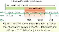
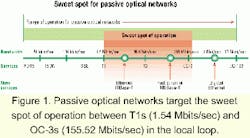
PONs aim to break the last-mile bandwidth bottleneck by targeting the sweet spot between T1s and OC-3s that other access-network technologies do not adequately address (see Figure 1). The two primary types of PON technology are ATM PONs and Ethernet PONs.The development of Ethernet PONs has been spearheaded by several visionary startups that feel that the ATM PON standard is an inappropriate solution for the local loop because of its lack of video capabilities, insufficient bandwidth, complexity, and expense. As the move to Fast Ethernet, Gigabit Ethernet, and now 10-Gigabit Ethernet picks up steam, Ethernet PONs will also eliminate the need for conversion in the WAN and LAN between ATM and Internet Protocol (IP).
Vendors are focusing initially on developing fiber-to-the-business (FTTB) and fiber-to-the-curb (FTTC) solutions, with the long-term objective of realizing a full-service fiber-to-the-home (FTTH) solution for delivering data, video, and voice over a single platform. While Ethernet PONs offer higher bandwidth, lower costs, and broader service capabilities than ATM PON, the architecture is broadly similar and adheres to many G.983 recommendations.
In November 2000, a group of Ethernet vendors kicked off their own standardization effort, under the auspices of the IEEE, through the formation of the "Ethernet in the First Mile" (EFM) study group. The new study group aims to develop a standard that will apply the proven and widely used Ethernet networking protocol to the access market. Sixty-nine companies, including 3Com, Alloptic, Aura Networks, CDT/Mohawk, Cisco Systems, DomiNet Systems, Intel, WorldCom, and World Wide Packets have indicated they will participate in the group.
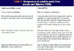
The economic case for Ethernet PONs is simple: Fiber is the most effective medium for transporting data, video, and voice traffic and offers virtually unlimited bandwidth. But the cost of running fiber "point-to-point" from every customer location to the central office, installing active electronics at both ends of each fiber, and managing all of the fiber connections at the central office is prohibitive. Ethernet PONs address the shortcomings of point-to-point fiber solutions by using a point-to-multipoint topology instead of point-to-point in the outside plant, eliminating active electronic components such as regenerators, amplifiers, and lasers from the outside plant, and reducing the number of lasers needed at the central office.
Unlike point-to-point fiber-optic technology, which is optimized for metro and long-haul applications, Ethernet PONs are tailor-made to ad dress the unique demands of the access network. Because this architecture is simpler, more efficient, and less expensive than alternative access solutions, Ethernet PONs finally make it cost-effective for service providers to extend fiber into the last mile and reap all the rewards of a highly scalable, low-maintenance, end-to-end fiber-optic network.The key advantage of an Ethernet PON is that it allows carriers to eliminate complex and expensive ATM and SONET elements. Traditional telecom networks use a complex multilayered architecture, which overlays IP over ATM, SONET, and WDM. This architecture requires a router network to carry IP traffic, ATM switches to create virtual circuits, add/ drop multiplexers and digital crossconnects to manage SONET rings, and point-to-point DWDM optical links.
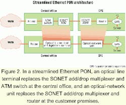
In the example of a streamlined Ethernet PON architecture shown in Figure 2, an optical-network unit (ONU) replaces the SONET add/drop multiplexer and router at the customer premises, and an optical line terminal (OLT) replaces the SONET add/drop multiplexer and ATM switch at the central office. This architecture offers carriers a number of benefits:
- Lowers upfront capital equipment and ongoing operational costs relative to SONET and ATM.
- Easier to deploy than SONET or ATM, because it requires less complex hardware and no outside plant electronics, which reduces the need for experienced technicians.
- Facilitates flexible provisioning and rapid service reconfiguration.
- Offers multilayered security such as virtual LAN closed user groups and support for virtual private networks (VPNs), secure Internet Protocol (IPSec), and tunneling.
- Carriers can boost their revenues by exploiting the flexibility and broad range of services supported by Ethernet PON, including delivering bandwidth in scalable increments from 1 to 100 Mbits/sec up to 1 Gbit/sec, value-added services such as managed firewalls, voice traffic support, VPNs, and Internet access.
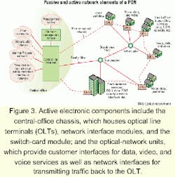
The passive elements of an Ethernet PON are located in the optical distribution network (also known as the outside plant) and include singlemode fiber-optic cable, passive optical splitters/ couplers, connectors, and splices. Active net work elements such as the OLT and multiple ONUs are located at the endpoints of the PON. Optical signals traveling across the PON are either split onto multiple fibers or combined onto a single fiber by optical splitters/couplers, depending on whether the light is traveling up or down the PON. The PON is typically deployed in a single-fiber point-to-multipoint tree and branch configuration for residential applications. The PON may also be deployed in a protected ring architecture for business applications or a bus architecture for campus environments and multitenant units.
Ethernet PON vendors focus on developing the "active" electronic components such as the central-office chassis and ONUs located at both ends of the PON. The central-office chassis is located at the service provider's central office, head-end, or PoP and houses OLTs, network interface modules, and the switch-card module. The PON connects an OLT card to up to 64 ONUs, each located at a home, business, or multitenant unit. The ONU provides customer interfaces for data, video, and voice services as well as network interfaces for transmitting traffic back to the OLT (see Figure 3).The central-office chassis provides the interface between the Ethernet PON system and service provider's core data, video, and telephony networks. The chassis also links to the service provider's core operations networks through an element-management system (EMS). The WAN interfaces on the central-office chassis will typically interface with digital crossconnects (DCSs), which transport non-switched and non-locally switched time-division multiplexing (TDM) traffic to the telephony network. Common DCS interfaces include DS-1 (1.5 Mbits/sec), DS-3 (44.7 Mbits/sec), STS-1, and OC-3; voice gateways, which transport locally switched TDM/voice traffic to the public-switched telephony network; IP routers or ATM edge switches, which direct data traffic to the core data network; and video network de vices, which transport video traffic to the core video network.
The ONU provides the interface between the customer's data, video, and telephony networks and the PON. The primary function of the ONU is to receive traffic in an optical format and convert it to the customer's desired format such as Ethernet, IP multicast, POTS, and T1. A unique feature of Ethernet PONs is that in addition to terminating and converting the optical signal, the ONUs provide Layer 2 and Layer 3 switching functionality, which allows internal routing of enterprise traffic at the ONU. Ethernet PONs are also well suited for delivering video services either in analog cable-TV format using a third wavelength or in IP video.
Because an ONU is located at every customer location in FTTB and FTTH applications and the costs are not shared over multiple subscribers, the design and cost of the ONU is a key factor in the acceptance and deployment of Ethernet PON systems. Typically, the ONUs account for more than 70% of the system's cost in FTTB deployments. In FTTH deployments, the ONUs represent approximately 80% of the cost.
The EMS manages the different elements of the PON and provides the interface with the service provider's core operations network. Its management responsibilities include the full range of fault, configuration, accounting, performance, and security functions.
The key difference between Ethernet and ATM PONs is that in Ethernet PONs, data is transmitted in variable-length packets of up to 1,518 bytes according to the IEEE 802.3 protocol for Ethernet, whereas in ATM PONs, data is transmitted in fixed-length 53-byte cells (with 48-byte payload and 5-byte overhead) as specified by the ATM protocol. This format means it is difficult and inefficient for ATM PONs to carry traffic formatted according to IP, which calls for data to be segmented into variable-length packets of up to 65,535 bytes. For an ATM PON to carry IP traffic, the packets must be broken into 48-byte segments with a 5-byte header attached to each one. This process is time-consuming and complicated and adds more cost to the OLT and ONUs. Moreover, 5 bytes of bandwidth are wasted for every 48-byte segment, creating an onerous overhead commonly referred to as the "ATM cell tax." By contrast, Ethernet was tailor-made for carrying IP traffic and dramatically reduces the overhead relative to ATM.In an Ethernet PON, the process of transmitting data downstream from the OLT to multiple ONUs is fundamentally different from transmitting data up stream from multiple ONUs to the OLT. Data is broadcast downstream from the OLT to multiple ONUs in variable-length packets of up to 1,518 bytes, according to the IEEE 802.3 protocol. Each packet carries a header that uniquely identifies it as data intended for ONU-1, ONU-2, or ONU-3. In addition, some packets may be intended for all of the ONUs (broadcast packets) or a particular group of ONUs (multicast packets). At the splitter, the traffic is divided into three separate signals, each carrying all the ONU-specific packets. When the data reaches the ONU, it accepts the packets intended for it and discards those intended for other ONUs.
Upstream traffic is managed utilizing TDM, in which transmission time slots are dedicated to the ONUs. The time slots are synchronized so that upstream packets from the ONUs do not interfere with each other once the data is coupled onto the common fiber. For example, ONU-1 transmits packet 1 in the first time slot, ONU-2 transmits packet 2 in a second non-overlapping time slot, and ONU-3 transmits packet 3 in a third non-overlapping time slot.Ethernet PONs offer many cost and performance advantages that enable service providers to deliver revenue-generating services over a highly economical platform. However, a key technical challenge for Ethernet PON vendors lies in enhancing Ethernet's capabilities to ensure that real-time voice and IP video services can be delivered over a single platform with the same quality of service and ease of management as ATM or SONET.
Vendors are attacking this problem from several angles. The first is to implement methods, such as differentiated services (DiffServ) and 802.1p that prioritize traffic for different levels of service. One such technique, Type-of-service (ToS) Field, provides eight layers of prioritization to make sure the packets go through in order of importance. Another technique called bandwidth reserve provides an open highway with guaranteed latency for POTS traffic, so it does not have to contend with data.
To illustrate some of the different approaches to emulating ATM/SONET service capabilities in an Ethernet PON, Table 2 highlights four key objectives that ATM and SONET have been most effective at providing: (1) the quality and reliability required for real-time services, (2) statistical multiplexing to manage network resources effectively, (3) multiservice delivery to fairly allocate bandwidth among users, (4) tools to provision, manage, and operate networks and services, and (5) full system redundancy and restoration.
Ethernet PONS are designed to deliver comparable services and objectives using Ethernet and IP technology. That has sometimes required the development of innovative techniques, which are not adequately reflected in literal line-by-line adherence to ATM or SONET standards and features.
The following techniques allow Ethernet PONs to deliver the same reliability, security, and quality of service as more expensive SONET and ATM solutions:
- Guaranteed quality of service using TOS Field and DiffServ.
- Full system redundancy providing high availability and reliability.
- Diverse ring architecture with full redundancy and path protection.
- Multilayered security such as virtual LAN closed user groups and support for VPN, IPSec, and tunneling.
Ethernet PONs are in the early phases of commercial development with initial trial deployments anticipated during 2001. Standardization efforts are already underway based on the establishment of the Ethernet in the First Mile study group and momentum is building for an upgrade to the Full Services Access Network (FSAN)-initiated ATM PON standard.
The stage is set for a paradigm-shift in the communications industry that could well result in a completely new equipment deployment cycle, firmly grounded in the wide-based adoption of fiber-optic and Ethernet technologies. This optical IP Ethernet architecture promises to become the dominant means of delivering bundled voice, data, and video services over a single network. Ethernet PON is an enabler for a new generation of cooperative and strategic partnerships, which will bring together content providers, service providers, network operators, and equipment manufacturers to deliver a bundled entertainment and communications package unrivaled by any other past offering.
Gerry Pesavento is senior vice president of advanced technology and Mark Kelsey is senior product marketing manager at Alloptic Inc. (Livermore, CA).
