Mode coupling receiver increases PON split ratios
By CHRIS PFISTNER AND DAVID PIEHLER
Fiber to the home or premises (FTTH or FTTP) deployments have now reached every continent and represent the premier wireline broadband access technology. Yet a large barrier to further FTTP deployments remains: the high first installed cost. While the equipment costs for optical access networks in the central office (CO) and at the customer locations have actually reached parity with DSL and cable equipment, the costs of digging trenches and deploying the actual fiber infrastructure remain high since they are driven by infrastructure investment dynamics rather than communication equipment price curves.
Therefore FTTP has become the architecture of choice for greenfield deployments (new housing construction) where no network infrastructure exists yet, whereas copper-based architectures still dominate broadband deployments in brownfield situations (overbuilding existing copper networks in established neighborhoods). That’s one key reason why countries with major building booms like China and some gulf states in the Middle East have seen a rapid increase in FTTP connections.
Once the FTTP infrastructure is deployed, network operators face another challenge: Since new customers are acquired one at a time, network use rate starts out low and might take a while to grow to attractive levels. Even Verizon, which has offered their FTTP service FiOS for more than five years now, achieves an average take rate of about 35%, and in some areas the take rate is lower. As a consequence, network operators are looking to reduce fixed networks costs – which are independent of the number of subscribers. One way of achieving this goal is by increasing the number of customers that share the same common equipment in the CO.
We’ll explain how a new type of OLT called mode coupling receiver (MCR) OLT increases the split ratio in a PON without increasing the loss in the upstream direction, thus serving a larger area of potential customers per OLT slot in the OLT line card.
Concept and building blocks of MCR
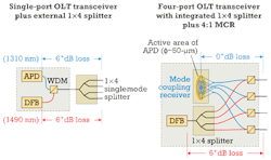
Figure 1 shows the concept by comparing a conventional GPON OLT followed by a 1×4 power splitter with a four-port MCR GPON OLT. The 1:4 split is chosen for illustration purposes, but higher split counts are also possible.
The MCR OLT leverages the fact that multiple singlemode fibers can be coupled with nearly 100% efficiency to a relatively large area detector. A 50-μm-diameter avalanche-photodiode surface has an active area of about 2,000 μm2 while the effective mode area within a singlemode fiber is less than 80 μm2. This concept addresses the dominant limiting factor for any PON link budget, namely the limited sensitivity of the burst mode receiver (BM Rx) at the OLT.
In the downstream direction, the power splitter remains and the transmit power needs to be increased to compensate for the additional insertion loss. In the case of a four-port MCR GPON OLT, that can be achieved by simply using higher-output DFB lasers, whereas higher-port-count MCR OLTs would require optical amplification to compensate for the additional split ratio. Each of the four output ports in Figure 1 represents a full GPON OLT port, whereas the four output ports from the power splitter on the left all have a 6-dB lower link budget.
MCR implementation using PIC technology
As mentioned, the concept of the MCR is not new.1,2,3 But the implementation using bulk-optic components made even a four-port device big enough to require either a full line card for an OLT shelf or a standalone 1U rack-mounted pizza box. These days the vast majority of OLT transceivers are pluggable SFP (GPON/GEPON) or XFP (10GEPON/XG-PON1) modules. The latest GPON OLT line cards can accommodate up to 16 SFP transceivers. To ease installation, the MCR OLT modules need to plug directly into the existing SFP OLT line cards.
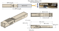
Conventional bulk optics will not fit in an SFP form factor, but emerging photonic-integrated-circuit (PIC) technology makes that possible. For example, NeoPhotonics and BT Innovate & Design recently demonstrated a four-port GPON MCR OLT in an SFP form factor by combining all the functionality shown in Figure 1 into a single photonic chip inside the SFP module.4
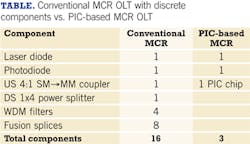
Figure 2 shows an early prototype (top left) with the MCR PIC enclosure protruding from the SFP cage. The photo on the right shows the MCR chip next to a standard GPON OLT SFP. The final form factor is shown at the bottom with the overall length of the MCR module increasing by only 13 mm over a standard SFP. A side-by-side comparison of the number of individual subcomponents in a conventional MCR setup versus a PIC-based MCR OLT is shown in the Table.
FTTP architectures, deployment strategies
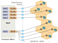
The upper section of Figure 3 shows how each of four serving areas with initially just one home connected still requires a dedicated conventional OLT transceiver in the OLT shelf. The MCR OLT shown in the lower section combines four PON outputs into one module that plugs into a standard OLT port in the shelf. Thus, one optical OLT port can serve all four areas.
This configuration cuts significant costs because, in addition to reducing the number of ports on the OLT line card by a factor of four, the cost associated with cards for common controls, switching, aggregation, and uplink, plus power and cabling, is cut by a factor of four as well. By enabling higher split ratios, the MCR OLT module offers substantial cost savings particularly in scenarios with low bandwidth use rates.
Optimizing bandwidth utilization
Network operators have always looked for options to maximize the number of users sharing the same infrastructure when rolling out broadband access networks. The easiest way to achieve that is by increasing the split ratio of any point-to-multipoint access network.5
The “bursty” nature of most data traffic ensures that broadband users typically experience a significantly higher data throughput than the mathematical average of the allocated bandwidth would suggest. Cable operators are masters at maximizing split ratios in their HFC networks; today a typical DOCSIS 3.0 service group passes 500 homes. With five (RF) channel bonding, ~200-Mbps downstream and ~120-Mbps upstream bandwidth are shared among all subscribers. A GPON, even when split among 128 subscribers, offers nearly an order of magnitude more bandwidth per subscriber than the nearest competition. When future services require higher bandwidth, the split ratio can be reduced.
The MCR OLT offers network operators a new option to increase split ratios without compromising their users’ broadband experience. In the case of a four-port GPON Class B+ MCR OLT, they can serve 4×32 = 128 users, and a Class C+ MCR OLT will take that number up to 4×64 = 256 users.
Moreover, all these calculations assume fully loaded networks. However, PONs are rarely fully loaded (in terms of bandwidth usage or customers connected), and the initial take rate can be as low as a few percent. We’ll outline how the MCR OLT lowers the network operator’s total cost of ownership over the course of the equipment lifetime.
Financial model
Most network operators use sophisticated financial models to determine total cost of network ownership for different deployment scenarios, considering capital expenditures (capex) and operational expenses (opex), and taking into account discount rates while analyzing cumulative cash flows and net present value (NPV).6
Figure 4 shows the cost savings of a GPON network rollout using four-port MCR OLTs compared to a rollout using conventional OLTs. All calculations are done using arbitrary currency units. Different network operators will use slightly different numbers in their network modeling, but the fundamental dynamics remain the same.
For the analysis in Figure 4, the following assumptions were made:
- Deployment runs over eight years.
- Capex of a fully loaded OLT port is 100 currency units (cu) in the first year (discounted for following years). The port cost includes the allocated share of common equipment like shelves, power, cabling, common controls, switching, aggregation and uplink.
- In the conventional OLT scenario, all four OLT ports are deployed in the first year to cover the entire service area.
- In the MCR scenario, one MCR OLT is deployed the first year to cover the entire service area. Every other year, a conventional OLT is added to address the increasing take rate in the network.
- To establish the base scenario, the cost of the MCR OLT is set the same as the conventional OLTs to illustrate the cost savings of a staged rollout. In real world deployments, MCR OLTs will carry a higher cost because of higher complexity and functionality.
- Opex for an OLT port is 10% of the initial capex per year.
- Discount rate is set at 10%.
In the conventional OLT deployment, all four OLTs are deployed in the first year, which leads to a 4×100 cu + 10% opex = 440 cu followed by 10% opex for the next seven years, bringing the total cost of ownership to 630 cu. In the case of the MCR deployment, the first year only requires an investment of 100 cu + 10% opex = 110 cu followed by yearly opex of 10% and additional capex (discounted) for the remaining three OLTs incurred every other year, bringing the total spend over eight years to 350 cu. Under these assumptions the total cost of ownership for the MCR rollout is almost 50% lower than for the conventional rollout. This simple analysis shows the impact of maximizing the split ratios per OLT in a PON rollout and avoiding stranded investment.
Keeping PON costs low
FTTP has become the premier wireline access technology of the 21st century, and GPON and GEPON represent the dominant network architecture. The biggest barrier to FTTP deployments remains the high first installed cost.
One common strategy is to keep split ratios high, especially during the initial deployment phase when take rates are often low. The MCR OLT serves exactly that purpose by optimizing bandwidth use. Only the application of PIC technology has enabled the implementation in an SFP form factor compatible with the installed base of GPON OLT line cards. This advancement offers network operators a new tool to leverage their installed base and reduce their installed first cost.
References
- B. De Vos, et al., OFC 2002, ThH1.
- N. Cheng, Z. Liao, and F. Effenberger, ECOC 2010, Tu.5.B.3.
- F.N. Raharimanitra, et al., ANIC 2010, AThC3.
- D. Nesset, et al., “GPON SFP Transceiver with PIC-based Mode-Coupled Receiver,” ECOC 2012, Tu.3.B.4.
- D. Piehler, ”PICs in PONs,” OFC 2012, NTu1J.6.
- R. Hülsermann, et al., “Applying a Discounted Cost Model and a Time-Dependent Demand Model to Access Network Cost Evaluation,” CTTE 2011, S3-3.
CHRIS PFISTNER is vice president of product marketing and DAVID PIEHLER is chief scientist at NeoPhotonics Corp.


