RF video delivery raises SBS issues
A significant advantage of FTTH is the technology’s inherent capacity and flexibility to support a wide variety of services. While copper-based low-bandwidth access technologies such as the various VDSL and ADSL variants are fundamentally limited to baseband switched digital video and IPTV and hybrid fiber/coax architectures are best suited to broadcast RF video transmission, FTTH can support either technology. This flexibility is a significant competitive advantage, and some wisely note that the unique ability to elegantly combine the two video delivery technologies puts FTTH in a class by itself.1,2 In particular, PON implementations such as BPON, GPON, and EPON are especially well suited to take advantage of the combined benefits of RF and IP.
A recent poll conducted by the U.S. Telecommunications Association indicates that network operators planning video services over FTTH are split nearly 50-50 in their choice to deploy RF or IPTV. Perhaps most interesting, hybrid RF/IP deployments have just recently begun in the United States, where RF transmission carries analog and digital broadcast and IPTV offers increased variety of video on demand and interactive content.
Transport and distribution of IPTV follow the same line of thinking as other IP services, although issues such as latency and packet loss do become much more demanding. These issues have been reasonably well addressed in a number of different forums. However, RF video transmission, while very well understood in the cable TV industry, has not received a great deal of significant treatment in the context of PON architectures. Particularly, the issues associated with optical RF video transport and distribution for FTTH networks are rarely addressed beyond a single overly simplified model. A look at the most common network configurations for RF video transport in FTTH networks reveals potentially significant optical limitations. Fortunately, the means to address these limitations currently exist.
The RF video overlay in a PON architecture can be implemented in a variety of different configurations. This fact is frequently overlooked in simplistic analyses of the limitations and requirements placed on video transport and distribution in FTTH.
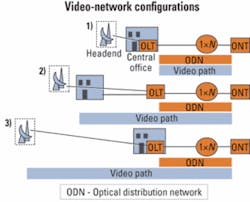
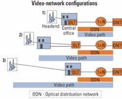
Three common implementations are illustrated in Figure 1. There are several commonalities between all three cases. Each complies with the requirements prescribed in the relevant ITU-T BPON and GPON recommendations (G.983.3 and G.984.1) for the “enhancement band” of wavelengths, supporting video-service transmission between 1550 and 1560 nm, although specific requirements and limitations on video transmission truly are given only a cursory review in the recommendations. Additionally, each case requires that RF video signals are amplified in the optical domain due to the relatively high received-power requirements at the ONT (typically -6 to -3 dBm) coupled with the high passive losses seen in the PON optical distribution network (ODN) between the OLT and subscriber premises-located ONT.However, there are also significant differences in the three cases. The illustrated cases clearly show that video signals may be required to cover much longer distances than just the reach of an individual PON.
Configuration 1 in Figure 1 is easily the simplest to understand and most trivial to analyze and is thus typically the most common configuration addressed in basic overviews of FTTH video service. However, it is not necessarily the most common configuration.
In this arrangement, the terrestrial video signal (regardless of signal format) originates from the same location as the PON OLT and primary voice/data network functions from a collocated video headend (HE). Here, broadcast video signals are received via a combination of aerial off-air antennas, large-diameter satellite dishes, and (sometimes) direct optical feeds from local broadcasters. Alternately, aggregated video content may be transmitted digitally from a remote location (sometimes called a “super headend” or “SHE”) and converted to RF at the collocated HE. All terrestrial signal generation equipment such as RF modulators, optical video transmitters, and optical EDFAs are housed in the same location as the OLT.
This configuration ensures that the RF video signal is only transported over the PON ODN, covering a standards-mandated maximum distance of 20 km. Optical losses encountered in this portion of the network are still quite significant, considering the impact of connectors, optical splitters, cabled fiber, and splices, along with allocated margins in the loss budget for aging and repairs. As a result, the amplified optical launch power requirements for RF video can range from 14 to more than 20 dBm to meet received power requirements. These power levels are obviously dependent on distance, choice of standard or specialized optics and electronics, design margins, and overall configuration of the PON ODN.
Configuration 2 in Figure 1 is quite similar to configuration 1, with optical video signals originating at a local video HE collocated with the local central office (CO). In this case, however, OLT optics and electronics are not centrally located at the HE/CO but are distributed through the field in remote terminals (RTs) or at electrical substations in the case of municipal utilities. This configuration is sometimes found in reasonably sized (several thousand households passed, or HHP) rural FTTH deployments with relatively low subscriber density (perhaps five to 20 homes per mile). ODN characteristics such as loss budget may be similar to configuration 1.
By remotely locating OLTs, operators can accommodate CO-to-ONT distances that otherwise would exceed the maximum PON ODN lengths determined by logical limitations and as defined in standards. Therefore, the total distance covered by the optical RF video signal can significantly exceed the total length of any individual ODN, as shown in Figure 1. In most cases, optical amplifiers will be located at both the HE/CO and at each RT, where video signals will be multiplexed with OLT signals onto a single fiber for each PON. Overall video-signal distances in such configurations can exceed 30-40 km.
Configuration 3 is commonly used in large (>10,000 HHP) FTTH network deployments. Here, a regional video HE is centrally located to serve a number of separate COs. The HE in this case is sometimes referred to as a video hub office (VHO).
This design somewhat resembles modern consolidated cable TV networks, with a single broadcast HE serving multiple local hub facilities over “trunk” or “supertrunk” lines. Video signals in this case will typically see the longest transmission distances of all the configurations, sometimes approaching 60-80 km or more between HE and ONT-well in excess of the maximum allowable ODN distance. Additionally, EDFAs will typically be placed at intervals of 20-40 km.
A standard singlemode optical-fiber infrastructure can present limitations in each of the RF video-overlay network configurations discussed above. Common throughout each of the configurations is the potential limitation of stimulated Brillouin scattering (SBS).SBS occurs when an optical signal excites the molecular structure of an optical fiber, generating an acoustic wave that backscatters a portion of the signal back onto itself. In simplified terms, a portion of the signal is essentially reflected backwards. That will obviously reduce the power received at the end of the network, but it will also impart severe noise and distortions onto the transmitted signal. Therefore, SBS limits the maximum amount of optical power that can be launched into a length of optical fiber by establishing a threshold above which RF video signals (both analog and digital) can be severely degraded.
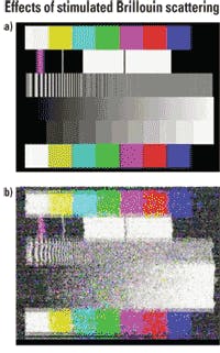
The impact of SBS on analog video-signal quality is clearly illustrated by the video screen captures in Figure 2, where the introduction of both noise and distortion is obvious. SBS is an issue in RF transmission since the minimum allowable received optical power levels for RF signals can be 10-15 dB higher than those for traditional baseband digital, thus requiring a commensurate increase in optical launch power. Even when more channel capacity is dedicated to QAM digital than analog, SBS can pose problems.
The effect of SBS has been identified for quite some time,3 and has been an issue in video transport networks such as supertrunk links built by cable TV operators for nearly 10 years (since the advent of linearized 1550-nm transmitters and low-noise optical amplifiers). Through various electronic techniques, transmitter manufacturers have mitigated the effect significantly by increasing the fundamental SBS threshold of video transmitters via various applications of high-frequency modulation. In fact, without some degree of electronic SBS mitigation, 1550-nm video transmitters would be practically useless, since they would only be capable of supporting power levels on the order of 6 or 7 dBm. However, these techniques have their limits, since the means used to increase an optical transmitter’s SBS threshold must be balanced against other signal degradations that can be induced.
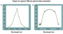
Figure 3 illustrates the output of a typical 1550-nm optical video transmitter with and without SBS suppression applied. Clearly, increasing a transmitter’s SBS threshold also increases its linewidth. As these signals propagate through fiber, chromatic dispersion and nonlinear effects such as self-phase modulation can wreak havoc on signal quality. As a result, the industry largely has learned to live within the limitations of SBS, all the while assuming that the capability of singlemode fiber (SMF) is set in stone.The SBS threshold of a system employing standard off-the-shelf video transmitters and standard SMF-considered as all ITU-T G.652-compliant SMFs, including those with reduced water peak attenuation-is commonly considered to be 16-18 dBm over a distance of 50 km. The SBS threshold actually increases with shorter distances, and as a result, situations such as those in configuration 1 can typically support optical power levels about 1.5 dB higher over a 20-km distance. Still, configurations 2 and 3 see little improvement in SBS threshold, since video-signal distances commonly exceed the maximum 20 km encountered by PON optics.
Recent improvements in the fundamental understanding of SBS behavior in optical fibers,4 however, have allowed the design of ITU-T G.652.D-compliant SMFs with significantly increased SBS threshold levels while maintaining backward compatibility with legacy standard SMF.5 By incorporating fibers with enhanced SBS threshold, network operators are seeing more flexibility in network architecture, video transmission equipment choice, and design budgets and margins.
Two capabilities can be realized by exploiting fibers with higher SBS threshold. The most obvious is the ability to increase optical powers in the network by removing attenuation pads or introducing higher output EDFAs. That can allow longer system reach and potentially allow for removal of some EDFAs in long backhaul links by increasing individual amplifier spans.
The less obvious advantage of a fiber infrastructure with increased SBS threshold is the ability to increase signal quality and reach without increasing the optical power relative to a standard fiber configuration. If the fiber itself has an increased SBS threshold relative to standard SMFs, then the SBS mitigation applied to the transmitter can be reduced, resulting in a narrower linewidth and less susceptibility to nonlinearities and dispersion. In this scenario, a link can be operated at the same optical power commonly used with standard fibers, with standard off-the-shelf transmitters and EDFAs, but the signal quality can be dramatically improved and much longer distances can be accommodated.
As the competitive video market begins to heat up, with new providers offering services over new FTTH infrastructures, a host of issues must be considered. Clearly, the mature transmission technology used in the cable TV world can be exploited to great advantage and even combined with new IPTV approaches to deliver a new breed of offerings. Some assessments estimate that the cost of a combined approach, using the strengths of RF and IP together, can actually be more cost-effective than deploying either of the two technologies alone.2
An appreciation of the various network limitations for RF and IP, including optical, electrical, and commercial implications, is key to maximizing video-service capability and minimizing cost and complexity. Full consideration of the various network architectures and deployment scenarios allows network operators to understand the issues before them and plan accordingly.Andrew Woodfin is market development engineering manager at Corning (Corning, NY). He can be reached at [email protected]. The author would like to thank A. Boh Ruffin, Srikanth Raghavan, and John Mauro of Corning’s Science and Technology division for their contributions and invaluable insight.
References
1. J. Farmer, “Video in the FTTH triple-play package: Broadcast or IPTV,” Lightwave, July 2005.
2. C. Knittle, “RF/IP Hybrid Network for Video Delivery over FTTP,” Proceedings of OFC (2005).
3. R. Smith, “Optical power handling capacity of low loss optical fibers as determined by stimulated Raman and Brillouin scattering,” Applied Optics 11, pp. 2489-2494 (November 1972).
4. A. Kobyakov et al., “Design concept for optical fibers with enhanced SBS threshold,” Optics Express 13, pp. 5338-5346 (July 2005).
5. “NexCor Optical Fiber Product Information Sheet,” Corning (July 2005).


