Low-loss PON designs yield cost-effective triple play
Passive optical networks are expected to serve 75% or more of U.S. fiber to the premises (FTTP) subscribers in the coming years. Most PON providers plan to offer voice, video, and data services to maximize return on investment. They desire a network layout that provides maximum reach up to 20 km on a single fiber with a 1:32 split-ratio close to the subscribers to consolidate centralized active equipment and minimize fiber costs.
An optical-path analysis plus systems testing has shown that supporting such a configuration with the triple play, including high-power RF analog video, is feasible and economical without the need for special high-power fibers. Minimizing loss within the optical distribution network (ODN) and using a full-spectrum singlemode fiber and splitters enables comparatively low-cost support of both current and future higher-bandwidth applications.
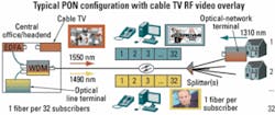
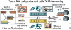
Today’s PONs typically serve up to 32 subscribers from a single fiber at the central office/headend (CO/HE) using one or two splitters close to the subscribers. Voice, data, and IP video can be transmitted from the optical line terminal (OLT) to the subscriber at 1490 nm. Data and IP video are transmitted from the subscriber’s optical-network terminal (ONT) at 1310 nm. Finally, in some cases a broadcast video overlay carried at 1550 nm is added to the PON using the same RF technology employed in cable TV networks. This 1550-nm RF signal can carry analog channels, digital channels, or both.
Migration to lower-cost, all-digital video is clearly occurring, but there will be some deployment of RF analog video overlay on PONs for a limited time. A typical PON architecture is shown in Figure 1.There are three standards for PON in use today. The broadband PON (BPON) and gigabit-capable PON (GPON) standards written by the International Telecommunication Union (ITU G.983.3 and G.984.2, respectively) specify the wavelength plan described above for voice, video, and data services and allow for the use of the 1360-1480-nm band for additional bandwidth and services.
An Ethernet PON (EPON) specification is included in the IEEE 802.3ah standard. It uses two of the three ITU PON wavelengths by specifying the 1310- and 1490-nm wavelengths for upstream and downstream services, respectively. IEEE specifications accommodate the use of the 1550-nm RF video and the 1360-1480-nm bands.
The fact that the three PON specifications referenced here all use or accommodate the same wavelength plan facilitates standardization of optical transceivers and lower costs. In addition, all three standards include full-spectrum G.652D fiber to enable low-cost CWDM overlays for additional bandwidth and services.
The manner of video delivery has a significant effect on PON design. These video approaches can be divided into two types: analog and digital. Analog video is cable TV-type video transmitted over the 50-550-MHz band using a modulated signal transmitted at 1550 nm, then amplified by an EDFA at the CO/HE.
The critical parameter to manage for analog video over FTTP networks is the carrier-to-noise ratio (CNR) of the signal received by the ONT. The FCC-specified minimum CNR is 44 dB, but to eliminate visible snow from the picture a CNR of >47 dB is required. Most FTTP providers specify a minimum CNR value of 46 or 48 dB.
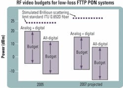
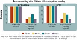
Achieving 48-dB CNR requires a minimum of -5 or -6 dBm of power received at the ONT with today’s receivers. Receiver manufacturers are working to improve CNR performance and claim that an additional 2-3 dB of improvement is possible and planned for such products. That would result in receivers supporting 48-dB CNR with only -8 dBm of received power. The combination of constantly improving transmitter stimulated Brillioun scattering (SBS) performance on standard G.652 fiber and receiver sensitivity performance is significantly easing the power and cost constraints of analog video (see Figure 2).On the transmit side, the SBS limit of the system can be a constraining factor. SBS results when very high optical power transmission into a relatively long length (>8 km) of fiber excites a sound wave along the length of the fiber, resulting in backscattering of a portion of the optical launch power. Power levels significantly greater than the SBS limit can increase noise at the receiver and degrade CNR and analog picture quality.
Fortunately, SBS is only a concern with high analog-channel-count systems and can be managed on standard G.652D fiber with low-cost transmitters developed for cable TV networks. (Fully digital systems require far less power at the receiver and thus far lower transmission power into the fiber.) For years, manufacturers of cable TV RF video optical transmitters have been able to cost-effectively and dramatically increase the effective power limit by utilizing cost-effective SBS suppression techniques, which have improved and will continue to improve over time, according to the manufacturers of such equipment. Today, standard video transmitters have an SBS rating of 16-20 dBm. However, these SBS ratings are at distances of 50 km or more, since these transmitters were initially designed to support cable TV backbones. As SBS increases with fiber length, these same transmitters have been shown to provide 2.5-dBm greater SBS suppression at 20-km distances.* Cost-effective transmitters optimized for 20-km FTTP networks also are becoming available that provide up to 23 dBm of SBS suppression for 20-km links.
Meanwhile, cable TV and FTTP providers are migrating to all-digital broadcast video systems to reduce power, cost, and content theft as well as increase effective bandwidth to add channels and accommodate the 4X higher-bandwidth requirement for high-definition TV channels. Digital video also eliminates the noise present in analog video and produces very clear pictures. Comparing the video quality of analog cable TV channels versus digital cable or digital satellite channels clearly shows the quality advantage of digital video.
There are two primary methods of transmitting digital video to FTTP subscribers: Carrying digital video on an RF signal at 1550 nm using 64-QAM or 256-QAM or transmitting video over IP at the 1490-nm wavelength.
As mentioned earlier, SBS is of no practical concern with digital video systems because they require much less power at the receiver and therefore much less power from the transmitter or EDFA. In the QAM case, the received power minimum requirement at the home is -12 dBm or lower, lowering the EDFA power by 7 dB. In the case of IP video, the signal is all-digital carried by Ethernet or ATM on the 1490-nm wavelength, and the received power for IP video is the same as that for the voice and data services at 1490 nm-typically from -20 to -30 dBm, depending on the transceiver specification. The result for IP video is a relatively low transmitted power of around 0 dBm.
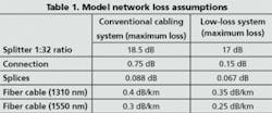
However, that doesn’t mean digital video is immune from potential impairment. Transmission from the OLT at the1490-nm wavelength can suffer from noise caused by stimulated Raman scattering (SRS) in the 1550-nm video signal. This noise can result in reduced CNR if the 1490 nm power exceeds certain limits. But such SRS has been shown to cause <0.25 dB of CNR degradation if 1490-nm launch power is limited to -1, +1, and +3 dBm for 155-Mbit/sec, 622-Mbit/sec, and 1.25-Gbit/sec downstream digital rates, respectively.* Modern optical transceivers accommodate such launch power constraints cost-effectively.The loss values model shown in Table 1 will be the basis for all subsequent analyses. The reach analyses will include two cases: the first being the use of a conventional cabling system and the second the use of a low-loss cabling system. In all cases, we assume a link configuration with four connections (mated connector pairs) and six fusion splices.
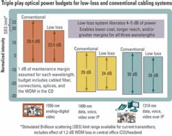
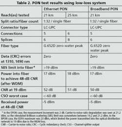
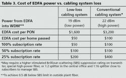
The reach for the BPON and GPON cases at 1310 and 1490 nm is calculated based on the power budget enabled by the optical transceivers used in the system, as specified in ITU G983.3 for BPON and G984.2 for GPON. The EPON reach is calculated with the IEEE link model used by 802.3ah to create the specifications for Ethernet in the First Mile PON. Standards-compliant power budgets were assumed for 1310- and 1490-nm voice/data wavelengths, and the 1550-nm RF video budget was 23 dB for both cases. Figure 4 shows the results of the modeling.Meanwhile, EDFA transmission power can account for a substantial cost per subscriber in an RF PON. Two approaches to support extended-reach with a single-fiber 1:32 split-ratio PON are using a low-loss cabling system and low EDFA power or using high EDFA power and a conventional cabling system having about 3-dB higher loss. Unless noted, a transmitter with a 16-dBm SBS suppression rating at 50 km (18.5 dBm at 20 km) is assumed. Other assumptions and results of this comparison are shown in Table 3.
Supporting a 20-km reach with a 1:32 splitter close to subscribers for single-fiber PONs providing triple play services, including full analog video, is possible with a properly engineered and designed optical system. Such a system meets this objective by using standard G.652D fiber, minimizing the optical-path loss of the ODN and using low-cost commercially available optical transceivers and transmission systems. Expensive high-power analog video systems can be avoided using strategies to enable lower-power and lower-cost EDFAs.
A low-loss low-power analog video overlay is shown to save up to $200 per subscriber compared to a high-power system and does not require special high-power fibers for current or future applications. Furthermore, a low-loss ODN across the full spectrum of wavelengths from 1260 to 1610 nm supports today’s applications and provides an economical upgrade path to future higher-bandwidth applications.
John George is systems engineering manager of FTTP and premises networks at OFS (Norcross, GA- [email protected]).
*G.H. BuAbbud et al., “Optical impairments, including Raman and Brillouin nonlinearities, in broadband WDM overlay single-fiber PONs - measurements, remedies, and design optimization guidelines,” presented at NFOEC 2003.