Variable optical power splitters create new apps
Optical power splitters based on fused-biconic-taper (FBT) and planar-lightwave-circuit (PLC) technologies have become highly developed over the last few decades. Due to the widely increasing deployment of optical MAN, fiber to the home (FTTH), and cable TV networks, the market potential for such power splitters is becoming larger and larger.
But current FBT and other optical-power-splitter (OPS) components can only provide a fixed optical split ratio. The evolution of telecommunications networks has created an increasing demand for variable OPSs. Development of variable OPSs has already been reported based on several technologies, including FBT, partly beam blocking or thermal waveguide couplers, and polymer-based PLCs. But these methods suffer from such disadvantages as small variable range, high polarization dependence, and low controllable resolution. Because their application value is limited, few if any of these components have been commercially available before.
However, it is now possible to create polarization-independent variable OPSs based on birefringent materials and polarization beam management. Prototypes of such devices have shown low insertion loss, polarization independence, and full variable range. In fact, prototypes of 1×2 and 1×4 variable OPSs using this technology have been constructed in both electronic and manual tune versions. The splitters can find use in a variety of applications.
To reduce FTTH access costs, many service companies have adopted PON technology, which enables several hundred users to share an optical line terminal (OLT) at the central office. In addition, service providers can have many users share one optical-network unit (ONU) at the customer end of the network. To add users, the carrier adds ONUs as necessary.
With the arrival of variable OPSs, carriers can now use a hierarchical connected architecture. In this kind of architecture, many users share one ONU, and many ONUs converge at one OLT through the OPSs. The number of users in each ONU can be different, and the path distances of each ONU to the OLT can be different too. Therefore, the optical-signal power of each ONU can be very different and can vary each moment. Thus, the variable OPS can provide many benefits for such an architecture. It can allocate the optical power of each ONU dynamically by changing its own power split ratio. It will improve network scalability, increase optical power efficiency, provide better network reliability, and lower investment risk.As shown in Figure 1, a plurality of M optical power distribution is realized serially. The first OPS receives an optical signal having a power level Pin. The OPS delivers a portion of this input power (Pout1) to the next serially connected OPS and a portion of the input power (Pin1) to its sub-network. The second OPS receives the signal from the first power splitter, the power level of which has been attenuated by a factor a1 due to attenuation loss on the line. The second and subsequent power splitters split the input power they receive in the same way as the first power splitter (i.e., between a first and second output). Each of the first outputs provides an input to the next OPS in the serial connection. Each of the second outputs provides an input to a sub-network. The last power splitter has only one output, corresponding to the second outputs of the others.
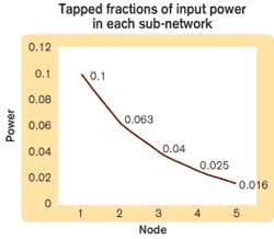
If the split ratio of each power splitter were fixed and equal, the power delivered to each sub-network (Pin) would become smaller and smaller from left to right along the line. Assuming an=0.7, Pn=0.1, Pin=1, M=5, the tapped fractions of input power in each sub-network is illustrated in Figure 2, which shows that the nodes differ greatly in power. The power of the last node is only about one-sixth of the first node. The power differences among nodes will undoubtedly cause problems for the transmission.But if the power split ratio of each OPS is variable, the input power of all the nodes can be made equal to about 0.086, with the power ratios set as follows: p1=0.086, p2=0.134, p3=0.222, p4=0.407, p5=1
Variable OPSs have other benefits for FTTH applications, including the allocation of power to each node according to its needs. Initially in an FTTH deployment, not every household in each node (such as an apartment) will subscribe. By using variable OPSs, the initial equipment investment and installation cost can be economized based on the principle of distribution on demand. It is worth mentioning that when all apartments are connected serially, the furthermost apartment has the biggest optical power loss as well as the greatest possibility of being disturbed. Variable OPSs can allocate more optical power to the apartments farther from the OLT to strengthen their anti-jamming ability.
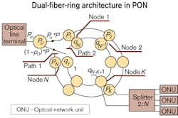
Self-healing rings are a popular protection mode in the MAN. The double fiber ring PON architecture shown in Figure 3 is an ideal application of the variable OPS.
The network architecture comprises a first set of N serially connected power-splitting centers connected at one end to receive a power signal and at another end to a termination point. Each splitting center has an output associated with a sub-network for delivering a portion of the power signal to that sub-network, wherein the power-splitting factor in each power-splitting center is variable. Thus, the portion of the power signal delivered to each sub-network is tunable.A second set of N serially connected power-splitting centers is connected in the same way. But each of these centers is associated with one of the first set of optical splitting centers such that the nth power-splitting center of the first set is associated with the (N-n+1)th of the second set. In addition, each pair of power-splitting centers has a respective output connected to a common sub-network, wherein only one of each pair of power-splitting centers receives the power signal.
In normal operation, the optical signals flow via one of the two fiber rings, for example, via the ring formed by the first set of optical splitting centers (i.e., the outer ring, where signals from the OLT to the ONUs are flowing in the clockwise direction, and the signals from the ONUs to the OLT in a counterclockwise direction). There are no signals on the inner ring.
When a cable break occurs, at least part of the power of the signal from the OLT will be directed into the standby ring-the ring defined by the second set of power-splitting centers (the inner ring, where signals from the OLT to the ONUs are flowing counterclockwise and the signals from the ONUs to the OLT clockwise). When a break occurs between the power-splitting pairs K and K+1, the split ratio p0 , the split ratios p1 in the outer ring, and split ratios q1 in the inner ring are adjusted to provide a constant output power at each tap to each sub-network.
In case of a cable break after node K, the constant tapped power at each node depends on K. The tapped fraction of the input power Pin (Y-axis) is a function of the position of the cable break (X-axis) when using variable OPSs.
In case of a cable break after node K in the proposed variable tap-coupler architecture, the tapped power per node is still constant but depends on K, as shown in Figure 3. For N=10 the tapped power varies less than 5.3 dB, which is much less than would happen in a system with nodes having a constant power split ratio p.
Variable OPSs also can play important roles in long-haul node-to-node networks. For instance, it can be used in optical line protection (OLP). There are two OLP schemes presently deployed: 1+1 and 1:1.
For 1+1 protection, a 1×2 optical splitter at the transmit end divides the signal for transmission over two paths. The receive end receives the signal from both routes and selects one of the two signals with another 1×2 optical switch. The advantage is that the system can monitor both routes at the same time and always selects the “best” signal. But the scheme always means 50% optical power loss.
The 1:1 protection approach requires an 1×2 optical switch at both the transmit and receive end. The optical signal is transmitted only in one route at the same time, so that the system avoids the loss of half of the optical power at the start.
Figure 4 illustrates how using variable OPSs to replace the 1×2 optical switches in the 1+1 approach can provide the advantages of both protection schemes. The system can transfer the optical power resource on the secondary path dynamically and monitor both paths at the same time.Furthermore, sometimes the primary and secondary paths are not in the same cable-perhaps not even in the same physical path-so protection can be provided in case of a cable break. Here, because the primary and secondary paths can differ greatly in distance, when these two paths are switched, the compensation and attenuation of optical power could prove essential for proper system operation, regardless of the protection scheme. That would mean that an optical amplifier (OA) and a variable optical power attenuator would be necessary devices. When the variable OPS is introduced, the variable optical power attenuator is no longer necessary; the requirement for the OA would vary depending on the application.
High-power amplifiers are widely deployed for fiber cable TV networks; they are a hotspot for EDFA development. The EDFA can be used to support the cable TV operations in multiple districts; an EDFA of 43 dBm is said to be able to support 20 residence districts. In this situation, allocating power of the EDFA evenly is actually a big waste because many of these districts are close to the central base station or have fewer residences. Here, using variable OPSs to replace common optical splitters will be convenient for network construction, lower cost, and provide better reliability and scalability.
Currently, FBT optical splitters with many different split ratios are designed and deployed according to the population and distance of the district, requiring a special order to the manufacturer’s factory. Because the split ratios are fixed, when an increase or decrease in the number of subscribers changes the power needed by each node, the splitters cannot accommodate it. When the link loss to an individual district increases for some reason, network maintenance becomes a problem. Undoubtedly, the application of the variable OPS here provides significant improvement.
Optical power splitters can even be used for the high-power amplifier itself. The amplifier output is formed by seven variable OPSs in a tree structure. It has eight power outputs with an LCD displaying optical power, in which the optical split ratios can be set manually by adjusting the variable OPSs.
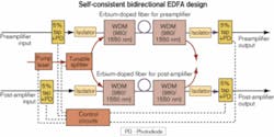
Variable OPSs can also play a key role in the design of intelligent OAs. For example, an economical self-consistent bidirectional OA design is shown in Figure 5. This dual-channel amplifying module can be used in a terminal line card to amplify both receiving and transmitting channels at the same time. For middle-reach transmission (up to 200 km), the line amplifier between the two terminals is not necessary. When the two channels travel down different paths, the module can adjust the receiving gain, delivering gain and noise performance agilely, providing the limited optical power resource with the best allocation. Such an amplifier would be ideal for ring or mesh MAN and CWDM topologies.The variable optical power splitter is the key to such an EDFA. With the variable OPS, when the pump light in the first stage is amplified and the noise performance is optimized, the rest of the pump light is used in the reverse pump of the second-stage amplification. The main parts include the pump source, the erbium-doped fibers, the WDM, and the isolator. The amplifier has only one pump source, from which the optical power is allocated to the erbium-doped fibers of the first stage and the second stage by the variable OPS. The control circuit controls the optical split ratio of the pump source and the pump power according to the monitor signals of the optical detectors in every input and output port, so it can automatically adjust its working situation to satisfy a 0-bit-error-rate system requirement.
By adjusting the power split ratio, the variable OPS can provide flexibility for optical networks to maintain power equilibrium, make use of optical resources effectively, and maintain the quality of network transmission. As dynamic networks become more popular, components that can meet this requirement become more important. Thus, variable optical power splitters should find wide application.
Wen Liu, Yun Zeng, Chen Long, Luo Yong, and Keyu Wu work at Accelink Technologies (Wuhan, China).


