With calculated EMB, SR 10G is guaranteed
More than ever, higher bandwidth and faster throughput are critical to business operations. IT managers have already adopted 10-Gbit/sec-capable networks for LAN backbone bandwidth aggregation and data-center applications. It is estimated that a majority of campus backbone networks will operate at 10 Gbits/sec in the next five years.
Both American and international standards now exist to define specifications for 10-Gbit/sec systems. Short-reach (SR) systems (300 m or less) take advantage of low-cost 10-Gbit/sec VCSELs and the high-bandwidth capacity of 50-µm multimode fiber (MMF) at 850 nm. Calculated effective modal bandwidth (EMBc) is a new bandwidth metric that provides several advantages in assuring robust 10 Gbit/sec transmission performance in these SR applications.
The cost and reliability of a system are the network developer’s most important considerations. In LAN applications, the availability of high-speed 850-nm VCSEL transceivers and new laser-optimized 10-Gbit/sec-capable 50-µm fiber has made the SR serial multimode system more cost-effective than alternative singlemode (SM) approaches.
The performance of an SR system depends on both the properties of the transceivers and the MMF. The requirements for fibers and lasers are specified by Telecommunications Industry Association (TIA) standards. The TIA Fiber Optic Working Group on Modal Dependence of Multimode Fiber Bandwidth (FO-4.2.1) developed the 10-Gbit/sec specifications based on the technical needs of the link and the manufacturing capability of the vendors to ensure product availability and multivendor interoperability.
On the transceiver side, the 10-Gbit/sec laser is required to have most of its power located in the core radius between 4.5 and 19 µm. Specifically, no more than 30% of the power should be located in the area that is <4.5 µm of the core radius-i.e., encircled flux (EF) is <30% for a core radius <4.5 µm). That effectively limits the power launched into the lowest-order modes of the MMF. On the other hand, the TIA standard also requires at least 86% of the power to be within a 19-µm core radius (EF >86% for core radius <19 µm) to prevent too much power being launched into the outer diameter of the core or into the cladding modes.
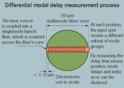
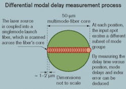
Given the cost-effectiveness and prevalent nature of 850-nm VCSEL transceivers, new MMFs are optimized at this wavelength to achieve low-cost system requirements. Different from the historical FDDI fibers with a 62.5-µm core size and LED sources at the 1310-nm wavelength, 50-µm MMFs have inherently much higher bandwidth and are able to support 10-Gbit/sec transmission at 850 nm while simultaneously maintaining the legacy 1310-nm requirement.The DMD method clearly indicates the relative delays between the modes and, therefore, the quality of an MMF. The DMDs need to be sufficiently small to meet the high system bandwidth and distance requirements for 10-Gbit/sec transmission.
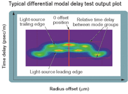
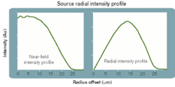
System performance is the result of the interaction between the input source properties and fiber modal structure. The former is characterized by the source radial intensity profile and the latter by the fiber DMD profile (see Figure 2), as measured using the TIA-455-220A standardized test method. From these measurements of source and fiber attributes, the EMB of a 10-Gbit/sec system is calculated.The source radial intensity is the near-field intensity weighted by the radial position (see Figure 3). The EF at a particular radius is the area up to that radius divided by the total area under the curve. Under the broad definition of the EF requirement, there is a wide range of power/intensity distributions supplied by the source manufacturers that offer 10-Gbit/sec 850-nm VCSELs. That has created many challenges in trying to predict and guarantee system performance practically and mathematically.
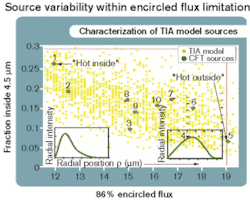
Figure 4 shows the distribution of 10-Gbit/sec lasers conceptually created for the TIA modeling work, along with a sample of 10 actual lasers used for anchoring the standard. Sources #1 and #5 represent two extreme lasers, which have power concentrated more to the center of the core and more to the edge of the core, respectively.
Assurance requires that the 10-Gbit/sec system operates without failure for these extreme cases as well as a variety of intermediate modal distributions. Some source manufacturers may tend to produce large-spot lasers, while others may produce small-spot ones, and the intent of the standards is to guarantee functionality for as broad a distribution of lasers and fibers as possible. Conceptually, each fiber could be tested with dozens of lasers to verify that it worked with each, but such an approach is impractical for many reasons. The EMBc method provides a technique for using a specific fiber measurement (the DMD) and a specific laser measurement (EF) to predict how any fiber will work with a set of lasers or how any laser will work with a set of fibers.
An important feature of the EMBc concept is that the mode power distribution due to the source can be represented by a weighted sum of DMD pulses, although the weighting is determined by the overlap of the intensity distribution and the modal structure of the fiber. Since any source can be accurately represented mathematically using a particular set of weighted DMD pulses, all source variability and the induced modal dependence of system performance can be tackled mathematically. TIA-455-220A Annex D provides a procedure for generating DMD weightings from the EF data, and a default set of weightings is provided for the 300-m 10-Gbit/sec 850-nm serial application based on the 10 actual lasers depicted in Figure 4.Incorporating the DMD information of the fiber and the weighted sum of the DMD launches as the source information, the output pulse information can be calculated. The bandwidth of this laser-fiber pair (EMBc) is then compared to the EMB requirements of the system. In summary, the main purpose of the EMBc is to ensure that the EMB of a fiber will meet the 10-Gbit/sec requirement for any mode power distribution consistent with the conforming lasers. The minimum EMBc is the minimum of the calculated EMB values for a fiber using a range of conforming lasers that spread over the spectrum of the EF, as indicated in transmitter sets 1-10 in Figure 4. It ensures that the fiber will work with all types of lasers meeting the EF requirement.
Because the properties of the source and fiber (and, more important, their interactions) are included, EMBc has many advantages compared to other bandwidth measures adopted to date for guaranteeing a system’s performance:
• Sound physics base and experimental verification. The EMBc process integrates the fundamental properties of light sources, the mode power distribution, and the MMF’s modal structure, using the weighted DMD pulses and fiber DMD scans. The physics used represent the true dominant factor of system performance, yielding accurate analytical results. Successful experimentation has been conducted to support and verify the approach.
• Ensures worst-case compliance. The minimum EMBc used to specify the fiber performance ensures that the MMF will work for almost all types of qualified sources, including the extreme hot-centered and hot-outside lasers. It is therefore a conservative and robust system performance metric.
• Flexibility and adaptability for different data rate and link length. The EMBc work originally developed for 10-Gigabit Ethernet (10-GbE) is also inherently appropriate for any other useful data rates and link lengths for applications such as Fibre Channel in data centers. As long as the correct inputs are defined for the source characteristics at the data rate of interest, the system performance can be predicted using the same calculation methodology reliably.
• Standards compliance and multivendor support. EMBc is a method widely supported by many fiber, component, and system vendors. Broad consensus was obtained during its adoption into the TIA and 10-GbE standards. This method is in the process of being adopted by International Electrotechnical Commission as an international standard.
Since publication of the IEEE 10-GbE standard, the TIA FO-4.2.1 Working Group has started working on scaling the EMBc bandwidth metric into other data rates and link lengths to meet the needs of various protocols. The proposed combinations include 1.25 Gbits/sec for 600 and 1,000 m, 2.125 Gbits/sec for 300 and 600 m, and 2.488 Gbits/sec for 300 and 600 m. Also mentioned were 10 Gbits/sec at 150 and 600 m.
The discussions are focusing on determining the fiber assumptions and laser-source mode power properties as major inputs to the model. The latter is important because it is generally believed the 1-Gbit/sec VCSELs have a larger spot size than 10-Gbit/sec VCSELs, rendering very different mode power distributions between the two. It is also agreed that the scope should include all of the 50-µm MMFs ranging from 500 to 2,000 MHz•km. A round-robin experiment may be proposed for final verification.
Driven by continuous bandwidth needs from the desktop in enterprise networks, 10-Gbit/sec systems are quickly being adopted by IT managers for campus backbone and corporate data centers. The SR approach using 850-nm VCSELs and the 50-µm laser-optimized MMF provides the most cost-effective method to meet the need. The EMBc metric offers the best performance guarantee for robust 10-Gbit/sec SR system transmission, and this metric is poised to be widely adopted for other bit-rate and link-length applications.
Y. Lisa Peng is manager, market analysis, strategic planning and analysis, at Corning Optical Fiber (Corning, NY); John Abbott is a senior engineering associate, advanced modeling and analysis, Corning Inc. (Corning, NY); and Doug Coleman is manager of strategic technology at Corning Cable Systems (Hickory, NC).
