Jitter testing gives ITU-T the shakes

A certain amount of noise or jitter is inherent in any digital transmission system, but such impairments become increasingly problematic at higher bit rates. At 10 Gbits/sec, every piece of equipment in the network must be accurately measured, but what happens when the jitter tester itself is not accurate? How do you verify the accuracy of the jitter tester? Agilent Technologies (Palo Alto, CA) and Anritsu (Richardson, TX) say they have solved the problem-through completely different means. The International Telecommunication Union (ITU-T) now finds itself with the unenviable task of deciding which test equipment giant is right if it can’t reconcile the two methodologies.
As previously specified by the ITU-T, a piece of operational equipment running at 10-Gbit/sec SONET rate should not exceed 100 mUI (milli-unit intervals) of intrinsic jitter, which is defined as the jitter generated by a single network element. Intrinsic jitter is difficult to measure because it involves relatively low levels of jitter amplitude. Test equipment used to test intrinsic jitter typically features a fixed-error accuracy of ±35 mUI-35% of the standard. The result is often inaccurate testing; good devices can be failed and bad devices can be passed, leading to disputes between suppliers and customers. “The industry has come to the conclusion that at 10 Gbits/sec, having a tester fixed error of ±35 mUI is unacceptable when the limit you’re trying to test against is only 100 mUI,” explains Ronnie Neil, marketing manager at Agilent’s Communications Network Services Division.
Unfortunately, determining whether a jitter tester delivers ±35 mUI accuracy in the first place has proven to be easier said than done, making the development of more sensitive devices a challenge. The ±35-mUI benchmark was derived through a measurement of the receiver and transmitter together; there was no way to calculate the accuracy of the receiver-the test equipment-only. Because jitter accuracy is an industry-wide concern, ITU-T Study Group 4 (SG4) has taken on the challenge of creating a receiver-only test to improve the accuracy and repeatability of jitter testing.
SG4 comprises representatives from test manufacturers and is responsible for the “O” documents that define test specifications. ITU-T O.172 defines jitter and wander measuring equipment for digital systems based on SDH. The study group has issued two proposals for determining jitter accuracy: Appendix VII, “Method for Verification of Measurement Result Accuracy” and Appendix VIII, “Method for the Characterization of Transmit Intrinsic Jitter.” Both appendices use an external instrument to provide signals with known amounts of jitter, and the ultimate goal of both is to determine how accurately the jitter receiver measures these signals. But how each accomplishes this goal is radically different.
Appendix VII. Developed by Agilent, Appendix VII describes a process for generating a signal with exactly 100 mUI of jitter amplitude. The procedure also specifies a method for varying the characteristics of that signal to simulate all the various noise-type jitter sources that exist in live networks.
“Let’s say we generate 100 mUI of amplitude with jitter characteristic A,” explains Neil. “We feed that into our jitter receiver, and it measures 105 mUI. We plot that [on a graph]. Then we transmit 100 mUI of jitter again, but this time with characteristic B. In this case, it reads 98 mUI. We plot that and do it again-100 mUI, but this time with characteristic C. In this way, we build up a map of how accurate the receiver is by plotting the results it provides with reference to that 100-mUI value, but against all the varying characteristics that cover all the types of jitter you would get in a live network.”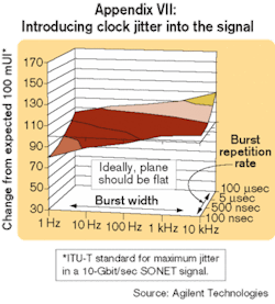
If you had a perfect jitter tester, the accuracy map would be perfectly flat and centered on 100 mUI, says Neil (see Figure 1). For every instrument that goes through production, Agilent is plotting an accuracy map and centering it around the reference value of 100 mUI. “What we’re seeing with these accuracy maps is ±10 or 11 mUI,” reports Neil.
Appendix VIII. Like the Appendix VII procedure, the Anritsu-developed Appendix VIII also uses a pattern generator to generate a signal. Unlike the Agilent method, the Anritsu method generates a jitter-free, high-quality signal (see Figure 2). Anritsu then employs a variety of electrical-to-optical (EO) converters that generate different amounts of pattern-dependent jitter (PDJ). “The key to the Appendix VIII process is that we use a standard, off-the-shelf, inexpensive sampling oscilloscope, and we’re going to measure the PDJ that is actually on the signal,” explains Jack Landau, marketing communications manager at Anritsu. “The sampling oscilloscope verifies the amount of PDJ that’s on that signal. Then you take that signal into the tester, and the jitter tester measures it. You compare the amount that the jitter tester measures with the amount that you verified on the scope, and the difference is the error.”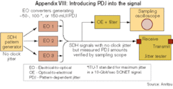
“The big pro for Appendix VIII is that it can be used to set up a calibration point in manufacturing,” asserts Jessy Cavazos, industry analyst with market researcher Frost & Sullivan (Richardson, TX). “The Agilent method is very accurate, but manufacturing managers do not have access to all the required equipment. Appendix VIII provides them with a quick way to calibrate.”
According to Agilent, however, Appendix VIII is the equivalent of estimating a single point on a receiver accuracy map; it provides only that single calibration point and no information on how the jitter measurement will behave under different jitter conditions. Moreover, explains Neil, “if you only take one point on that map and plot it against the reference value or calibrate it against the reference value, then you may actually not have centered the whole map around that value; you may have picked an extreme and centered that around the reference value.” Calibration of the receiver to a single point may enhance repeatability, say Agilent representatives, but it cannot match the accuracy of the Appendix VII method.
The folks at Anritsu have similar problems with the Agilent procedure. “Appendix VIII measures the reference side directly using a sampling oscilloscope, and that provides the reference value that we’re calibrating against,” says Landau. “It’s an independent measure, not dependent on the tester at all. Whereas in the Agilent method, there’s a lot of math and a lot of good calculations that theoretically tell you what the jitter amount is-clock jitter in their case-but there’s no apparent way to verify it. There’s no point in that process where you put some other instrument on there and you measure it and say, ‘Yes, this is what it is.’”
The Agilent method introduces clock jitter into the signal and employs a proprietary process for removing all PDJ, while the Anritsu method introduces PDJ into the signal and does not deal with clock jitter at all. “Our position is that the major portion of jitter in a real optical signal that would really be transmitted in a real environment is pattern-dependent jitter,” says Landau. “That’s why we believe it’s important to use PDJ and not clock jitter as the means of verifying the accuracy of the tester.”
“So which way is it going to go?” muses Cavazos. “Appendix VII or Appendix VIII? The key to understanding where the market is going to go may actually be Acterna,” she reports. As the third member of the ITU-T SG4, Acterna has been a key participant in the development of both appendices.
“We can say from the Acterna standpoint that we agree to both methods,” asserts Andreas Alpert, product manager at Acterna and member of the ITU-T SG4. “We contributed to both methods, and we will use both methods for our test equipment.” Acterna will use Appendix VII procedures in its R&D and manufacturing processes to calibrate its jitter meters and generate accuracy maps and use Appendix VIII procedures to verify the quality of its jitter test meters. “We will offer both to our customers,” he adds.
While Agilent clearly backs Appendix VII and Anritsu is solidly behind Appendix VIII, Acterna’s adoption of both methods indicates that they are not mutually exclusive-an opinion shared by the ITU-T. “Apparently, the ITU-T has judged that both of these are plausible methods, because they will include both of them as appendices in the standard,” notes Landau.
At press time, an interim meeting of SG4 was planned for late last month in the United Kingdom to clarify both appendices before the general meeting in Geneva next March. According to Landau and Alpert, both Appendix VII and VIII should obtain official approval at the general meeting.
The work of the ITU-T SG4 does not end there, however. “As you go up in speeds, the required accuracy and repeatability of jitter testing becomes more and more important,” contends Frank Ferrara, business development manager at Acterna’s Optical Transport Division. “As important as it is at 10-gig, it will be even more important at 40/43-gig.” The next step for SG4 will be defining the parameters of a receiver test at these higher bit rates.