Laser-optimized MMF for 1/10-GbE campus backbone
Systems engineers are routinely asked two questions: How do I determine the type of fiber needed for my campus backbone? And how many fibers do I need to install? Both questions require some analysis to help network designers make the best decisions. A network model can be created to evaluate different installation scenarios based on Gigabit Ethernet (GbE) and 10-GbE as the LAN protocol.
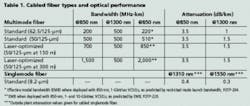
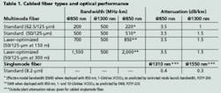
Before GbE, fiber type was an easy decision in campus design. Standard 62.5/125-µm multimode fiber (MMF) was used for any application up to 2,000 m and network speeds up to OC-12 (622 Mbits/sec). Singlemode fiber (SMF) was the choice for everything else. Multimode 62.5-µm fiber was recommended based on the TIA/EIA-568A standard—GbE and 10-GbE changed these rules. Laser-optimized 50-µm MMF was introduced with increased performance for 10-GbE, and the fiber performance was included in the TIA/EIA-568B standard.A summary of the fiber types and their optical performance is shown in Table 1. Different fiber parameters are listed. Overfilled launch bandwidth is used for LED electronics operating over MMF. Effective modal bandwidth (EMB) simulates operation on MMF based on the use of GbE or 10-GbE VCSELs at 850 nm.
Before determining the fiber type, network designers must decide on the cabling topology for the campus—one way to do that is to create a campus backbone model. The backbone model assumes each building contains multiple floors with a minimum of one telecommunications room per floor. All distances are in meters and include the length from the building entrance to the main communications room. All network analysis is based on a GbE building-to-building fiber backbone with provisions for 10-GbE.
The design of the cabling topology can be separated into three smaller steps to help the network designer make the best choice. First, consult the TIA/EIA-568 standard, which gives design rules for cabling the campus backbone. They include the following:
- The backbone cabling shall use a hierarchical star topology.
- There shall be no more than two levels of crossconnects (XCs) in the backbone cabling.
- Connections between any two horizontal XCs shall pass through three or fewer XCs.
- Maintain length requirements between the main XC, intermediate XCs, and horizontal XCs. For MMF, the maximum length between the main and intermediate XCs is 1,700 m and the maximum length between the main and horizontal XCs is 2,000 m.
It should be noted that standard 62.5-µm fiber and standard 50-µm fiber cannot support GbE or 10-GbE at 2,000 and 1,700 m as stated in TIA/EIA-568.
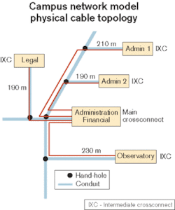
The second step is to determine the location of the main, intermediate and horizontal XCs. Before determining the location, the network designer must define the function of these XCs. The main XC serves as a crossconnection for first-level backbone cables, entrance cables, and equipment cables. The intermediate XC provides the crossconnection between first-level and second-level backbone cabling. The horizontal XC serves as a crossconnection of horizontal cabling and other cabling such as backbone or equipment cabling.In the campus model, assume each telecom room acts as the horizontal XC and connects to the building's intermediate XC. Next, the intermediate XCs connect back to the main XC in a physical star topology. The key decision is how to determine the location of the main XC, which is usually dictated by where most of the servers, switches, and routers are housed. If a certain building is already chosen based on these criteria, then all length calculations will be from that point. If any of the buildings can act as the main XC, then the network designer needs to determine which building is centrally located to minimize cable lengths. In Figure 1, selecting the "Administration Financial" building as the main XC and the other buildings as intermediate XCs yields a practical solution since the "Admin" building is centrally located on the campus.
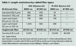
The third step is to determine the fiber lengths. Though the cable is deployed as a physical star, other logical topologies can be considered, such as a ring or mesh network. To get a better understanding of the fiber distances, it is a good idea to construct a matrix that defines the fiber distance between any two buildings in the backbone. Remember that the Admin building is the main crossconnect for the campus, so all network connections flow through it. Table 2 illustrates this concept for the campus model in Figure 1.Based on the cable routes chosen for the campus model, the next step is to determine the fiber types. Since the network designer is concentrating on the campus backbone (building-to-building links) and GbE and 10-GbE technologies, the designer needs to look at length restrictions based on fiber type. This comparison is shown in Table 3. This type of analysis should also be used for the building backbone.
The GbE distances shown in Table 3 are a function of the fiber core size and the associated EMB. Several questions must be addressed: The 62.5-µm fiber has a larger installed base, so is it worth switching over to 50-µm fiber? What should the fiber mix of multimode to singlemode be? To answer these questions, the network designer must apply a logical networking scenario to the physical topology. In the campus model, a redundant point-to-point logical star topology is implemented. This architecture uses redundant electronics in all buildings to reduce single points of failure. In this example, the campus backbone is sized for GbE with provisions for migrating a 10-GbE network.The first step in implementing this architecture is to determine the fiber counts for the GbE backbone. Since the logical topology is point-to-point, the distances in Table 2 are used.
In the analysis that follows the network designer is evaluating how to migrate the backbone from 1 to 4 Gbits/sec using standards-based Ethernet trunking (IEEE 802.3ad). The campus will also utilize two switches per building.
To analyze this network, the network designer needs to look at how many fibers and what types of fiber (MMF and SMF) are lit when migrating the network to the logical topology. First, look at multiple building-to-building (main XC to intermediate XC) links and calculate the number of fibers utilized. The result is that 16 fibers are needed for each building-to-building link for the 4-Gbit/sec Ethernet backbone (2 links per building × 2 fibers per GbE link × 4 GbE trunks per link = 16 fibers). To implement a redundant star topology, four fibers are needed for each building-to-building link for 10-GbE migration.
The next step is to determine the number of multimode and singlemode fibers needed to implement this redundant star topology. Again, refer back to Table 2 for the building-to-building link lengths and compare the fiber type to the length restrictions for GbE and 10-GbE in Table 3.
Analysis is then conducted by trying to size the backbone to maximize the use of 850-nm VCSELs for serial GbE and 10-GbE. Even though MMF can operate at the 1300-nm window for GbE and 10-GbE, it is more cost-effective to operate at 850 nm over MMF due to the lower cost of the 1300-nm GbE and 10-GbE cards. It should also be noted that 1300-nm solutions for GbE and 10-GbE require four wavelengths to operate over MMF.
The last step is to determine the final fiber counts for each cable. Although we have shown the minimum fiber counts to migrate the backbone trunk from GbE to 4-Gbit/sec Ethernet and ultimately 10-GbE, what about other applications that might run across the network? Applications such as security video, card readers, videoconferencing, and control systems require additional fibers. Unless all applications are going to operate over an IP network, the network designer will also need to add spare fiber in the cables. Spare fiber can run anywhere from 25% to 100% in a campus design. In this campus model, a 50% spare fiber rule is used.
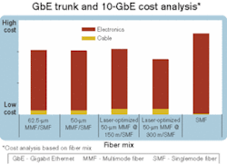
The fiber mix can change based on the type of MMF and the length restrictions for GbE and 10-GbE. To determine which fiber mix is the most cost-effective, the network designer needs to analyze the cost of the GbE cards, 10-GbE cards, and fiber types for the campus backbone. Here are the costs:
- Cables that contain standard 62.5-µm or standard 50-µm fiber are assumed equal in cost. The laser-optimized 50-µm fibers have an associated premium (based on list price).
- Long-reach (LR) cards for GbE over SMF typically cost twice as much as GbE short-reach (SR) cards for MMF (based on list price).
- LR cards for 10-GbE over SMF typically cost $1,000–$5,000 more than the 10-GbE SR cards for MMF (based on list price).
The laser-optimized 50-300 MMF and SMF mix is 30% cheaper than operating this network over SMF only, even though the cable cost is higher than the other solutions. SMF can support GbE up to 5 km and 10-GbE up to 10 km at 1310 nm, but the higher premium paid for this solution is a direct result of the much higher price of the GbE and 10-GbE cards that operate over SMF.
After adding the spares, the cable counts are sized at 36 MMF and 12 SMF. Distributors typically stock cables that are multiples of 6 or 12 fibers, and many hybrid cables (MMF/SMF) are also stocked.
The last part of the analysis is to determine the break-even point for using laser-optimized 50-µm MMF versus a SMF solution. While SMF is less expensive, the electronics costs are higher. Using the same campus model (Figure 1), the building links were adjusted from 200 to 1,000 m and the electronics costs were added for each length.
The results show that for a GbE and 10-GbE infrastructure, the point where an all-SMF solution is the same cost as the laser-optimized MMF/SMF solution is about 1,000 m. At <300 m, network designers can achieve an average savings of 32% by using a mix of laser-optimized (50–300-m) MMF/SMF instead of an SMF-only solution. At lengths between 300 and 600 m, the savings is about 16%.
While there are many different fiber types, some simple rules can be applied to help network engineers design LANs. For links ≤1,000 m, a laser-optimized 50-µm MMF should be considered for GbE applications, but SMF is needed for 10-GbE applications. A laser-optimized MMF for 1/10-GbE applications is also appropriate for any links <300 m. These rules of thumb are based on migrating the network from GbE to 10-GbE, while maintaining consistency in the fiber mix.
Some key points can be drawn from this analysis to help make the best decisions when determining fiber types and fiber counts for a campus network.
David Kozischek is manager of strategic technology at Corning Cable Systems (Hickory, NC).
