Requirements, challenges applying optics in a backplane environment
New generations of communications, computing, and storage equipment are not constrained to a shelf, rack, or cabinet and can be distributed across many shelves or cabinets separated by tens of meters. While designers have various interconnect options available to them to integrate these distributed subsystems, they will more frequently look toward optics as an alternative to electrical interconnects.
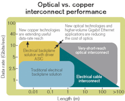
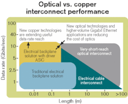
Based on analyses of performance and cost, there tends to be a crossover point where optics within a system makes sense. This point is generally distance-dependent because of the superior signal integrity that optics provides over greater distances.
While card-to-card interconnects (1 m or less) are today solved electrically, for longer distances (>100 m), optics always has been the principal interconnect technology by providing single-fiber connections from the front panel at high speeds (>2.5 Gbits/sec). For this purpose, there are a variety of mature, tested, and reliable optical-interconnect products available, including LC, FC, ST, and SC. As system-level data-rate requirements exceed 5 Gbits/sec, the crossover point moves toward shorter distances (on the order of meters) and short-range optics begin to look attractive. Rack-to-rack interconnects fall into this distance category.To address this opportunity, the optics industry has been working to innovate new interconnect solutions. The same considerations of installation cost, bandwidth, path to upgrade, cable volume, electromagnetic interference, and maintenance, which drove the replacement of copper with fiber in longer-distance applications, are motivating the use of optical interconnects at progressively shorter distances within systems. But there are additional requirements such as mechanical, maintenance, repair, and cleanliness that exist when optics are considered for use within the box (see Figure 1).
Communications/computing systems in design today use line-replaceable modules connected to each other with a backplane to form the system. The benefits of this architecture are well known but generate special requirements for connectors that mate the modules to the backplane. These functional requirements include the ability to:
- Perform a field-replaceable "blind-mate" connection, since it is not practical to manually reach into the chassis slot to latch a connector.
- Handle the mechanical tolerances that exist in the chassis so the connection can be made reliable and repeatable without damaging the connector components.
- Coexist with electrical connectors and accommodate their mating tolerances without binding or compromising either component's performance.
- Be compatible with a range of fiber and ferrule types, including singlemode and multimode fiber and MT and 1.25-mm ceramic ferrules.
- Address the unique cleanliness challenges that exist in the chassis.
Unlike electrical connectors, which rely on friction between the electrical card edge devices to keep the cards in place, optical connectors generally require special latching to ensure proper coupling and control any forces exerted when mated. This type of latch and release system, when correctly sequenced, can provide a very reliable blind-mate coupling between the daughtercard and backplane. The user is unaware of any latching or disengagement that takes place, with the end effect mimicking the insertion of a standard electrical card. Once mated and latched, any forces generated by the optical-ferrule springs will be contained within the connection system. This approach to latching removes the forces exerted on the backplane that could lead to more complex latch and chassis design.
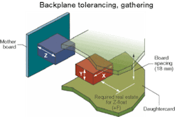
Optical connectors need to float in all three dimensions (X, Y, and Z). This movement enables the connector to gather and align the daughtercard and backplane within the tolerance range of the card as it is inserted and latched. It is critical that the optical connector does not limit mating of any electrical connectors that exist on the card edge and should therefore be thought of as the slave to the electrical-connector position. Specifically, it is the X and Y movement or float that allow for gathering, while the Z movement overcomes issues related to electrical wipe. This wipe is required to counteract accumulated tolerances within the enclosure itself; however, some wipe is always required in an electrical interconnect to break through oxide layers on the contact surface. Design factors such as board uniformity, planarity, positional tolerancing, board lock location, component tolerancing, and connector binding play key roles in the final position of the electrical connector in relation to the backplane. So for the two systems to work in harmony, one connector system must have guidance and float that exceeds the other, or potentially the competing systems will bind or limit the movement of the daughtercard (see Figure 2).Float in the X and Y axes can occur in either the daughtercard or backplane. It's important that the float be present at all times. It can be argued that the Z-float optimally should be placed on the daughtercard side, and the benefits are numerous.
First, the space required behind the backplane can be minimized because it isn't required to provide room for movement of the connector and exposed cabling. Second, a more rigid and stable interconnect can be made during mating. In early systems, where the Z-float was done by a "slideable" inner shroud within a housing on the backplane, a fully mated and populated system with exposed cables could generate enormous side loads that induced optical loss due to the weight of the cables themselves or the way the cables were managed. Also, exposed cables could be readily bumped or snagged, again introducing momentary spikes or system loss. A third benefit of shifting the float to the daughtercard side is to permit the use of low-profile interconnects on the backplane, such as flexible optical circuits with unexposed cabling or integrated optical waveguides fixed within the backplane, which may be seen in future systems.
Given the uncertainty of Z-positioning and considering that fiber interconnects require physical butt-coupling, it is desirable to use latches that set the longitudinal position of the mating ferrules and springs while simultaneously providing freedom in the Z-direction. To do that successfully, the optical mating sequence should be established before the electrical sequence.
Extreme-mating forces in excess of 150 lb can be generated when joining high-density electrical connectors due to the number of contacts being engaged and displaced. To overcome this force, manual cam latch mechanisms (card ejectors) are attached to the edge of the daughtercard and used to physically seat the board into the chassis and lock the board in place during use. These devices do not provide a great deal of user feedback other than a go, no-go, type of feel. With that being the case, if any given connector is not properly aligned under such loads, the likelihood of destruction is high. Therefore, it is critical that the individual connectors be precisely aligned before the latches have the ability to fully engage.
Since optical connectors by their nature have a tendency to be fragile, this alignment should occur prior to the electrical connectors mating to ensure no damage occurs when the cam latches are engaged. Furthermore, due to the difference in butt-coupling versus wipe, it's best to isolate any additional force spikes that may occur due to the optics themselves being mated. By staggering the mating sequence of the optics versus the electrical, it's possible to provide smoother board installation while not exceeding the overall force for which the cam latches are rated.
To accommodate a variety of electrical connectors and have a product that is easily leveraged into new technologies, it's essential to maximize the float to ensure compatibility and limit the possibility of large insertion-force spikes if peak insertion forces for the optical and electrical connectors overlap. To provide this functionality, Z-travel on the order of 3–7 mm is desired, which requires that the slave device (the optics) move in relation to the electrical device. Otherwise, the components could be crushed under the force of the lever arms if any misalignment occurred.
For Z-float to occur, a slideable mechanism is usually used to free the optical-connector assembly from its corresponding mounting means, which then allows the connector to travel freely to the point where the electrical connector bottoms or within the range of the electrical connector's wipe. Even though the optical connector is free to slide within a given range, it is still held captive by the optical subsystem latching, which maintains the positive force between the butt-coupled ferrules while ensuring the optical subassembly is recoupled to the optical assembly upon daughtercard disengagement. This type of mating, as mentioned earlier, exerts "zero force" when fully coupled, since there is no continual pressure being exerted on the backplane once the optical connector has disengaged and moved in relation to the electrical connector. There are several connectors on the market that currently function in this manner.
In most systems, the latch and float mechanism is integrated into the plastic of the connector body, reducing part count. Connectors are then built up by the increment of the connector, typically four MT ferrule groups. Other systems modularize the latch and float system from the connector function to optimize material usage, density, and scalability, also allowing for the mix of MT and single-fiber-ferrule technologies.
The requirements driving increased density directly impact the number of ferrule backing springs within the system, forcing designers of single plastic housings to redesign their systems to handle the new cumulative force. Alternately, similar housings must be stacked side-by-side, in the end causing a loss in usable card space. Segregating the latches from the optical housing, however, removes the need for the complex integrated latching components while providing an opportunity for modular stackable components. Through this modularity, a great deal can be gained without substantial sacrifices or unnecessary overhead. With separable connector plugs and independent latch modules, it is quite simple to develop custom designs that eliminate the need for specialty tooling and assembly equipment while providing a vehicle for fast manufacturing cycles and scalability.
While mechanical-tolerance issues are somewhat common to both electrical and optical backplane connectors, optics has an additional and unique challenge requiring clean interfaces to maintain an acceptable level of optical performance. Today's systems generate tremendous amounts of heat and require large airflows to keep the components cool. Typical airflows can be in excess of 60 cubic ft/minute (cfm) per slot and can peak at over 80 cfm per slot, translating into airflows in the chassis of up to 600 cfm. Typically, the only filters in the airflow are electromagnetic interference screens that do not stop smaller dust particles. Examples of contamination that can accumulate on the fiber surface include debris from product, manufacturing processes, package material, operators, and air quality.
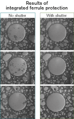
The bottom line is that contamination can build up on components within the box. Any interconnect solution needs to address these effects. Typically, ferrules are unprotected during mating and therefore exposed to contamination. The only recourses are routine cleaning and the use of protective dust caps while the connector is not being used. New innovations are now available that integrate the protection into the connector, and one solution is to address ferrule protection at the outside of the connector design and keep the ferrule endface as isolated from sources of contamination and handling damage as possible.
Keeping the ferrule protected from handling damage and contamination results in reduced cleaning cycles, easier cleaning, and less chance of replacing cables from damage due to debris. Figure 3 shows the benefits of a shroud-and-door system for a connector plug exposed to debris in a dust chamber.John Lehman is optical product development manager, Sepehr Kiani is principal optical design engineer, and Richard Roth is principal optical design engineer at Teradyne (Nashua, NH). They can be reached via the company's Website, www.teradyne.com.
