Interleavers make high-channel-count systems economical
Interleaver/de-interleaver components come in a variety of formats, enabling DWDM systems designers to use relatively inexpensive technology.
Bob Shine, Ph.D., and Jerry Bautista, Ph.D.
Wavesplitter Technologies
As most people reading Lightwave already know, the Internet has created an explosion in the amount of information transmited over telecommunications networks. According to the research firm RHK Inc. (San Francisco), roughly 1 million terabits/month are currently transmitted over telecommunication networks, with a forecasted growth to >15 million terabits/month in 2003.
While this explosion has created many new opportunities for service providers, it has created a challenge for system integrators and component manufacturers to offer higher-bandwidth systems. Both higher bit rates and higher-channel-count DWDM systems are being pursued aggressively to meet these bandwidth requirements. While existing technology and products can often be stretched to meet next-generation requirements, innovative new components are needed, as well. That's particularly true in the highest-bandwidth applications, where both high bit rates (10 Gbits/sec or even 40 Gbits/sec) and dense channel spacings are being pursued simultaneously due to the extremely stringent dispersion requirements in these systems. Let's examine a critical component, the interleaver/de-interleaver, which enables very-high-channel-count DWDM systems.
An interleaver/de-interleaver is essentially an optical router that allows existing DWDM filters designed for operation at wide channel spacing to be extended to system designs with narrow channel spacings in the range of 50 GHz or even less (see Figure 1). In the simplest case, the interleaver combines two sets of channels into one densely packed set with half the channel spacing. In reverse, the de-interleaver routes the single input set of channels into two output streams with twice the channel spacing.This single-stage interleaver can be cascaded in a binary fashion to create additional devices. For example, a 1x4 de-interleaver allows a set of channels with 50-GHz spacing to be routed to four output fibers with 200-GHz channel spacing. In this way, an interleaver can be combined with existing DWDM filters to immediately extend its application to narrower channel spacings or take advantage of specific performance characteristics. This capability is particularly attractive for long-haul system designs that require the highest-bandwidth solution. For this application, the design cycle and cost of new higher-bandwidth systems can be reduced by combining existing thin-film filters or array waveguide gratings with an interleaver to create a system with twice or four times the channel count of systems using just the filter or gratings themselves.
The interleaver has obvious applications for long-haul DWDM systems, where the highest channel counts are being deployed. However, the modularity of the component is attractive for regional metro applications where first-installed costs are critical. For the de-interleaver shown in Figure 1, not all of the four outputs have to be used initially. For example, a 1x4 de-interleaver designed for a 32-channel DWDM system will have eight channels on each output fiber of the device. The initial system could be deployed using one output fiber with just eight channels, and additional sets of transmitters and DWDM filters could be added to the unused interleaver/de-interleaver fibers when the bandwidth is required. Of course, the initial transmitters installed would need to have the stability required for the full-channel-count systems, but that does create an intelligent way to provide scalability in a system.Another application of an interleaver in the metro environment is to add/drop a set of channels at a node. In this case, the set of wavelengths on one de-interleaver output fiber can be designated as the drop traffic and demultiplexed while the other sets of wavelengths are express traffic and travel through to the next node. Although the majority of the traffic is express, the transmission through multiple interleaver/de-interleaver pairs places demands on their performance to minimize channel mixing and crosstalk.
While the previous discussion of long-haul and metro applications demonstrates the need for interleavers, it is worthwhile to examine the economics of the device, as well. A direct comparison with other approaches is difficult due to some of the different performance features; however, a key economic benefit of an interleaver design is that it allows lower-cost, older-generation filters to be used in a higher-channel-count DWDM system.
Consider a 16-channel system designed with a channel spacing of 100 GHz. Using current market values for the price of 100-GHz thin-film filters, the cost of the 16-channel DWDM filters is roughly $15,000. This price is quite high since the 100-GHz thin-film filters are relatively new with low yields and limited production availability. An alternative is to use a 1x2 de-interleaver with 200-GHz thin-film filters on the output fibers of the de-interleaver. Using the same market information, the cost of these DWDM filters is roughly $8,500, creating a price differential of $6,500. Since the cost of a 1x2 interleaver is much less than $6,500, there is a clear advantage to using the 1x2 de-interleaver and 200-GHz filters.
Clearly, the economic advantage of interleavers only increases for higher-channel-count systems. This advantage will continue into the future, since even though the price of 100-GHz filters will drop, filters with wider channel spacings will always be further down the cost curve than newer, denser filters and will have better availability.
When evaluating interleavers, the first parameters examined are the insertion loss, passband shape, and crosstalk performance for the desired channel spacing.
As with all components, and especially with interleavers since they are cascaded with additional DWDM filters, the lower the insertion loss, the better. A uniform, flattop passband shape is also very desirable to minimize channel-power variations as the signal wavelength drifts. Any initial imbalance in channel power will cascade as the signals pass through multiple amplifiers and affect the signal-to-noise performance of the system.
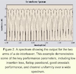
Often, a compromise is made between achieving a flattop passband shape and the insertion loss, since additional filtering elements are often added to an original sinusoidal passband shape to achieve a uniform flattop spectral response. Finally, the crosstalk performance of the device is critical since the interleaver/de-interleaver is used as the front-stage filtering device and determines the crosstalk performance for the assembly. While additional DWDM filters are used on the output of the de-interleaver, these filters have a wider passband and cannot significantly improve the adjacent channel-crosstalk performance. A spectra for an interleaver is shown in Figure 2.
Once these three basic parameters meet the design goals, there are a number of other parameters to consider. The device must be centered to the ITU wavelength grid, not just at one location but over the full wavelength range of the system, often tens of nanometers. If a passive technology is chosen, the wavelength drift of the device over the temperature range should be considered and the worst-case wavelength offset used to analyze the system performance in terms of passband and crosstalk. Active devices, while requiring additional control electronics, offer very-high-channel accuracy over the full operating-temperature range as well as the opportunity to actively compensate in the event of long-term laser aging. Since the interleaver/de-interleaver is used to filter the entire wavelength range of input channels, the channel uniformity is of concern. To meet the channel accuracy and uniformity requirements, a separate device for the C- and L-band is used, although ideally one device would cover the full-channel spectrum.As mentioned previously, the highest-bandwidth systems are increasing both the bit rate and channel count in the systems. Current bit rates of 10 Gbits/sec and next-generation bit rates of 40 Gbits/sec place an extremely tight requirement on the dispersion of all components. While there are currently many different technologies being pursued for interleaver products, the dispersion performance will probably be a critical factor in the relative success of the different approaches.
To be successful, the component must not only have a low dispersion value at the center ITU wavelength, but also maintain this low value over the full useful passband of the device (i.e., the dispersion value should not reduce the usable passband). Interleavers based on low-dispersion material such as fiber are expected to meet the dispersion requirements of even the highest-bandwidth systems.
In a sense, the reliability requirements could be viewed as a form of technical performance. But that's such a major concern, it deserves its own discussion. While some form of Telcordia Technologies (formerly Bellcore) reliability testing is required on all telecommunications components, the interleaver/de-interleaver is at the core of a DWDM system and will handle multiple terabits/sec of traffic. This amount of traffic is a significant revenue stream to the carrier, and the carriers and system providers will want to understand the basic technology used in the interleaver in detail with possible failure mechanisms identified and resolved.While the technical performance is a major concern when choosing components, more and more system integrators are evaluating the manufacturability of different designs. This evaluation involves questions of the raw materials and their availability as well as a discussion of yields with the manufacturer.
In general, a simple design using commonly available raw materials has an advantage over designs using specialty material, since there are less likely to be supply or yield issues. Also, a customer would like to have confidence that the technology can easily progress in future generations of devices and meet the current need. In one case, a manufacturer demonstrated a fiber-based 2.5-GHz interleaver.1 While a 2.5-GHz device is clearly not needed today, it does show that the all-fiber technology used in that device can be applied to future product generations and also gives confidence that 50- or 100-GHz devices are relatively easy to manufacture, since they are not on the bleeding edge of that technology.
As is common for a new class of devices, there are a number of different technical approaches to interleavers, with no clear technical winner as yet. The general principal behind interleavers is an interferometric overlap of two beams. The interference creates a periodic repeating output, as different integral multiples of wavelengths pass through the device. The desired channel spacing of the device is set by controlling the fringe pattern. Manufacturers today use fused-fiber interferometers, liquid crystals, birefringent crystals, and other more exotic technical approaches to build interleavers.
Probably the simplest design in terms of raw material and technologies is a fused-fiber Mach-Zehnder interferometer.2 In this design, the interference is created by using an unequal fiber-path length between two 3-dB couplers. By carefully controlling the path-length difference, the channel spacing can be set to the desired value and matched very well to the ITU grid. Because of the all-fiber design, this technology has very low loss, uniform response over a wide wavelength range, very low dispersion, and minimal polarization-dependence effects.
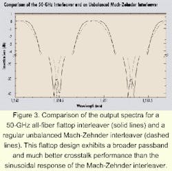
Liquid crystals and birefringent crystals act by creating an effective path-length difference for the different polarization states in the crystal (the ordinary and extraordinary ray) and filtering them with a polarizing element. The ordinary and extraordinary rays traveling through the crystal experience different refractive indices and hence different retardations. When the input wavelength experiences an integral number of full-wave retardation between the two polarizations, the signal will be transmitted through the exit polarizer, while other wavelengths will be routed to a secondary output. Of course, the input signal does not have a defined polarization, so extra components must be included to achieve the desired performance for any random polarization state. In both cases, the output pattern of these devices will exhibit a sine-squared pattern.Various manufacturers provide improvements to the general sine-squared interferometric pattern to differentiate their product performance. The flattop performance of one such device is shown in Figure 3 and contrasted to a sinusoidal Mach-Zehnder output device as previously dis cussed.3 This flattop device is an all-fiber device and exhibits very low insertion loss, typically <0.6 dB for a multiplexer and <1.6 dB for a demultiplexer.
In the past, this low insertion loss could only be achieved for a sinusoidal spectrum; to obtain a flattop spectrum, the insertion loss was reduced by apodizing the output with either an additional fiber or thin-film filter. In the device shown in Figure 3, the 0.6-dB insertion loss is achieved even with a 0.5-dB passband covering >50% of the channel spacing. Additionally, the crosstalk performance maintains a level of <-25 dB, even allowing for some drift of the signal wavelengths. As shown, other devices such as the Mach-Zehnder interferometer can achieve the same crosstalk level, but this level is obtained only for a very narrow wavelength range. If any allowance is made for drift of the signal laser, then the crosstalk performance suffers very rapidly.
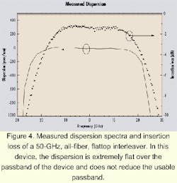
There are a number of other parameters of interest besides insertion loss, passband width, and crosstalk, and it is instructive to examine what can be achieved for a state-of-the-art device. Dispersion is a critical parameter for the highest bit-rate systems designed for long-haul applications and is dependent on the particular interleaver technology chosen. The all-fiber flattop interleaver discussed here has all the advantages of fiber and is expected to have one of the best dispersion parameters available. As with many of the other parameters, the value is critical not only on the ITU grid wavelengths, but also over some passband to allow for signal drift.
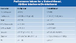
The performance of an all-fiber interleaver is shown in Figure 4, demonstrating a very low dispersion value over a wide useful passband. This performance will be required for 10-Gbit/sec and future 40-Gbit/sec high-channel-count DWDM systems. A full list of performance parameters is shown in the Table.
The Internet has created an explosive growth in traffic over telecommunications networks, and system integrators are increasing both the bit rate and channel count available in their systems. These advances require not only improvements in current technology, but new classes of components, as well. The interleaver/de-interleaver is one component that will allow very-high-channel-count systems to be designed.
Among the many approaches available, the second-generation all-fiber approach meets all the design goals of the system integrators, even for very-high-bit-rate designs. It offers very low insertion loss, wide flattop passband, good crosstalk performance, low PDL, and extremely good dispersion performance.
Dr. Jerry Bautista is chief technical officer and senior vice president of technology, and Dr. Bob Shine is director of marketing at WaveSplitter Technologies (Fremont, CA).
- J.C. Chon, H. Luo, C.H. Huang, R. Huang, J. Chen, and J.R. Bautista, "Expandable 50-GHz and 100-GHz dense wavelength division multiplexers based on unbalanced and cascaded-fiber Mach-Zehnder architectures," Tech. Dig. National Fiber Optic Engineers Conference, NFOEC'99, 1999.
- C.H. Huang, H. Luo, S. Xu, and P. Chen, "Ultra low loss, temperature-insensitive 16-channel 100GHz wavelength-division-multiplexers based on cascaded all-fiber unbalanced Mach-Zehnder structure," Conference on Optical Fiber Communication 1999, TuH2, pp. 79-81, 1999.
- C.H. Huang, Y. Li, J. Chen, E. Sidick, J. Chon, K. Sullivan, and J. Bautista, "Low-loss flat-top 50-GHz DWDM and add/drop modules using all-fiber Fourier filters," to be published in Tech. Dig. National Fiber Optic Engineers Conference, NFOEC'00, August 2000.


