Architecture and design of function-specific, wire-speed routers for optical internetworking
The complexity of a CIDR route lookup dramatically changes with the total number of routes in a route table. The nested nature of the addressing scheme causes a logarithmic change in lookup time with increased table size. Wire-speed algorithmic CIDR route lookup is nontrivial, since it involves translating an algorithm into hardware (such as an application-specific integrated circuit) and ensuring that it provides deterministic convergence under worst-case traffic conditions. A second challenge is to keep the jitter (i.e., the variation in algorithm convergence timings) bounded so as to limit latency within the network.
Packet classification is the key element of flow processing. Packets may be classified based on a parameterized set of metrics that may involve multifield packet header analysis. The parameters are usually specified by a user in conjunction with resource information that may be derived from routing protocols.
Flows in connectionless networks are determined by grouping packets that have common application-layer or session-layer information. A flow can be based on information transacted between a particular source and destination IP address or a TCP/UDP socket. Flows can also be based on DiffServ code points or type of service bits. Fundamentally, classification of like packets based upon information contained within each of them constitutes a flow.
DiffServ, or "Differentiated Services," deserves further explanation. DiffServ results from IETF initiatives to specify a means of providing end-to-end QoS in a connectionless packet-based network. The IPv4 packet header comprises a byte that consists of a 3-bit type of service field and a 5-bit field that provides 32 extra code points for marking packets to denote various levels of service. These DiffServ labels may be generated from source nodes in the network and may be altered by intermediate routers to shape network traffic. DiffServ is meant to provide a granular means of differentiating classes of service at the network edge.As mentioned earlier, a flow can be identified by various parameters, including DiffServ labels and application (TCP/UDP) information. Edge flows with granularity are termed microflows. An example of a microflow would be the classification of all packets of a certain TCP/UDP socket that originate from a particular IP address, or all RTP traffic destined for a certain IP address. Once a packet has been classified at the network edge and has been identified with a particular flow, it is forwarded out of the particular routing device onto the next level of aggregation within the network.
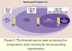
Figure 2 shows a multi-edge Internet model that illustrates the various levels of aggregation occurring at different points in the network and the rough route and flow metrics at these points. It is important to recognize the inefficiency of multiple examinations of the same flow of packets at various aggregation points. In fact, as we approach the backbone, data pipes get larger and packet arrival rates increase, making it impractical to perform deep-packet examination within the core. Additionally, the core may be operating on a different link-layer protocol such as Asynchronous Transfer Mode (ATM).Enter macroflows. A macroflow consists of a logical grouping of similar microflows. For instance, all packets entering a backbone or core device that have similar microflow information (e.g., DiffServ labels) may be grouped into a macroflow and can be metered, policed, and engineered efficiently. The concept of hierarchy in flow management and QoS classification has led to the use of Multiprotocol Label Switching (MPLS) as a means to manage and engineer macroflows.
MPLS was initially conceived to be a mechanism that unified the IP and ATM domains at the Internet core. It has, however, also become a powerful traffic-engineering tool. At the simplest level, MPLS allows core traffic to be engineered at either a circuit level via an ATM switch or at a packet level. The actual physical tag may denote an ATM virtual channel that has prescribed traffic behavior, or it may be used as a way to abstract Layer 3 microflow information and engineer macroflows at the core.
Path discovery involves the use of routing protocols. Routing protocols such as RIP, OSPF, or BGP-n are inter-router information-exchange mechanisms that build and maintain packet-forwarding tables used by the packet-forwarding blocks to physically route traffic and by policy and flow software to maintain and update flow tables. These protocols include algorithms that use value metrics based on a variety of parameters. An example is a network distance-vector metric, i.e., the closest network entity that has a path to the final destination. Other metrics used to build tables include latency and reliability.
In an IP network, the network-layer functions drive the QoS assigned to various types of traffic. QoS is applied via traffic engineering, which involves three distinct mechanisms:
- Admission control. This mechanism acts on incoming traffic that has been categorized by the network layer to ensure that all flows of information meet predetermined profiles (arrival rates), which in turn are determined by service-level agreements.
- Traffic shaping and bandwidth management. In this case, flows and other related parameters are used to determine when and at what rates various types of packets egress the system. Queuing becomes an essential part of the shaping and bandwidth management.
- Congestion control. All network devices are expected to experience congestion. While QoS is generally thought of in terms of prioritizing outgoing traffic, the avoidance of congestion is a key mechanism often sidelined or forgotten. Large, time-varying traffic patterns coupled with service overlays on the infrastructure could potentially cause network outages. Controlling congestion involves statistical coloring of traffic based on network and application layer information. Usually, processes such as random early detection (RED) monitor the state of various queues within the system and start to drop packets based on their capacity. It is important to note that drop processes such as RED can be modulated by weights that are user-supplied.
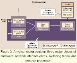
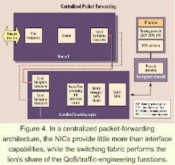
It is extremely important to note the path-discovery process time constant is on the order of 10 to 100 msec, while that of the packet-forwarding process scales with line rates (1/129 nsec at OC-48c). The large time-constant difference between these processes presents a logical opportunity for first-order partitioning-separation of the packet classification and forwarding paths from the routing control path. Subsequent architectural decisions involve further partitioning of the packet classification/forwarding paths.
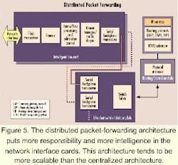
There are two broad methods generally followed: centralized packet forwarding and distributed packet forwarding. Key factors that drive the choice of approach include scalability, protocol support, and power.The basic concept of distributed packet forwarding is illustrated in Figure 5. NICs essentially assume the role of a full router. They comprise all the hardware, including the PMD and link layer, but are also fully equipped with packet-processing functionality as well as local QoS and traffic engineering. The switch fabric is purely optimized for nonblocking transport of packets across line cards and does not include any sophisticated QoS/traffic-engineering functions.
A summary of the differences between centralized and distributed packet forwarding-as well as the implications of these differences-appears in Table 1.
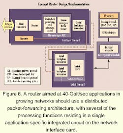
Let's look at relevant requirements and explore "first-cut" architectural partitioning for a backbone routing device capable of line-rate performance at 40 Gbits/sec. Specifications for the functional requirements at a system level are contained in Table 2. Thus, most of the discussion within this section explores architectural and component-level implications of these requirements.As stated previously, scalability, performance, and power requirements drive system partitioning. A distributed packet-forwarding architecture clearly lends itself to a more scalable system. The distributed architecture allows for building-out of a maximum capacity chassis and backplane and de-couples the scaling of the network layer from the switch fabric. It's possible to take a "divide and conquer" approach to solving system performance and scaling issues by:
- Reducing the complexity of the switch fabric and making it an ultra-fast, highly integrated, dedicated data-transport layer.
- Building a chassis with an optical backplane (fiber) that can scale as high as 20 Gbits/sec per link.
- Decoupling network layer from switch fabric allowing for maximum flexibility in scaling each independently.
