Ending wavelength power struggles with planar multichannel VOAs
Planar-lightwave-circuit VOAs offer higher levels of integration, reliability, and systems control in DWDM networks.
Dr. Vivek Tandon and Jim McGonigal
Kymata Ltd.
DWDM was initially deployed in the network core for point-to-point transmission. Today, wide spread deployment is occurring in the metropolitan, access, and even the data markets to carry fiber-connection, Gigabit Ethernet, and Escon traffic. DWDM technology will continue to expand into other markets, including cable networks and passive optical networks.
As the use of DWDM technology increases, the ability to control and monitor the power levels of the wavelength channels is becoming an increasingly important function. Power levels are measured and adjusted at the output of the transmitters, the input of the receivers, and both the output and input of the optical amplifiers. Why is it necessary to adjust the power levels of wavelength channels?To lower systems' costs, designers strive to maximize the bit rate per wavelength and the number of wavelengths, while reducing the regeneration and optical-amplifier sites. Maximizing the transmitted power of the signal helps to reduce the number of optical amplifiers. The total laser power within an optical fiber is constrained by two effects, however.
The first effect results because infrared light coincides with the optical-fiber-transmission spectrum, which is capable of causing damage to the human eye's cornea and lens. Hence, the maximum power transmitted down the length of an optical fiber should fall below 17 dBm as defined by the American National Standards Institute (ANSI 136.1). This standard is based on safety, so that in the event of a fiber break, the engineer repairing it is not blinded.
The second limitation is the physical nature of silica molecules, which results in an effect known as stimulated Brillouin scattering (SBS). SBS is a nonlinear effect appearing in systems involving high laser output powers such as those used in DWDM networks. SBS is caused by light being backreflected from an acoustic wave, which in turn results from the interaction of the light with the acoustic vibration of the silica molecules. Once the threshold power for SBS is achieved, all subsequent increases in power are completely backreflected, causing system degradation.During the installation of a DWDM network, careful attention is needed to ensure that the combined power level of all the channels does not exceed SBS and eye-safety limits. In addition, the power level of any one channel must not be so excessively high that it overwhelms the other channels.
With the early DWDM systems, an engineer was sent out to all the DWDM terminals and optical-amplifier regenerator sites to add channels, which helped to average down the individual wavelengths of the system. As DWDM systems with higher channel counts continue to be rolled out and more flexible networks are achieved through the deployment of reconfigurable add/drop multiplexing, remote power control is required, dictating the need to move away from fixed attenuators toward those that are dynamically variable.
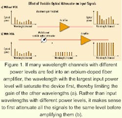
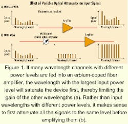
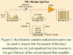
Optical amplifiers are very sensitive to the optical input power of the signals, which varies as the number of DWDM channels increases or decreases. The most commonly used optical amplifier, the erbium-doped fiber amplifier (EDFA) has a gain of around 20 to 35 dBm beyond which the amplifier saturates. If many wavelength channels with different power levels are fed into the EDFA, the wavelength with the largest input power level will saturate the EDFA first, thereby limiting the gain of the other wavelengths as shown in Figure 1. Rather than input wavelengths with different power levels, it makes sense to first attenuate all the signals to the same level before amplifying all to the same levels.Figure 1 is an oversimplification of the real effect induced by an amplifier. The gain spectrum of a typical amplifier is not flat; as a result, signals at different wavelengths get unequal amounts of amplification. This effect is commonly termed spectral-gain tilt and is more prevalent in wideband amplifiers. Two methods can be used to reduce spectral-gain tilt. One is through the use of expensive gain-flattened amplifiers, which offer a flatter gain response over a larger wavelength range. The second method is through the use of attenuators (preferably variable). Attenuators can be used to ensure that the powers of the input wavelengths are not just equalized but also inverse to the gain flatness of the amplifier being used (see Figure 2). Even when flat-gain amplifiers are used, the use of attenuators helps to relax the amplifiers' flatness requirements.
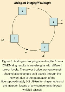
If the typical launch power of a signal from a directly modulated laser is around 5 dBm and the receiver sensitivity is around -30 dBm, the available power budget is 35 dBm. The power budget per wavelength channel is reduced as it travels through the network due to the attenuation of the fiber-approximately 0.2 dB/km for singlemode-and the insertion losses of any components through which it passes.
For example, in Figure 3 at Node B, the power of l1 is higher than that of l2 by the amount a + b where a is the attenuation of the fiber between nodes D and C, and b is the attenuation passing through node C. While the receiver has a sensitivity of -30 dBm, its dynamic range is likely to be 15 to 20 dBm. Therefore, when the power of l1 is higher than -10 dBm, an attenuator is necessary at either the output of the laser or at the input of the receiver to ensure the power level is maintained within the dynamic range of the receiver.
While both fixed and variable optical attenuators (VOAs) are in use today, VOAs offer the greatest flexibility and control. Currently, most VOAs are bulky single-channel devices that occupy large amounts of rack space and are expensive and cumbersome to manufacture.The most common VOAs, with moving parts, tend to work by altering the optical path using collimators at both the input and the output to the VOA. In this case the optical path is varied by either adjusting the focus of the collimators using a small motor or by blocking the beams of light be tween the collimators using an eccentric cam. Alternately, variable neutral-den sity filters or optical mirrors are used, in which case the filter/ mirror is made to either deflect or absorb light out from the collimated beam, resulting in attenuation (depend ing on its physical location). Unfortunately, the effect of having moving parts means that these devices tend to be difficult and complicated for volume manufacturing, requiring micromachining techniques for assembly and fiber alignment. Typically these methods also suffer from high optical power attenuations.
Static fiber-based VOAs with no moving parts that use thermal, electro-optic, or magneto-optic effects to alter the attenuation of the device are also available. If component supply is going to keep up with demand, then more cost-effective ways to mass-manufacture VOAs are required.
One approach to achieving significantly lower costs per function is to adopt planar-lightwave-circuit (PLC) technology. PLCs are essentially optical circuits laid out on a silicon wafer using a combination of flame-hydrolysis deposition, low-pressure chemical-vapor deposition or plasma-enhanced chemical-vapor deposition, and reactive-ion etching. The most popular platform used to create the waveguide is that of silica-on-silicon. The primary reason is that once the planar-waveguide device is created, it will need to be connected to other components within the overall DWDM system using optical fibers. Matching the silica to the fiber is relatively straightforward, because silica matches the refractive index of the fibers and hence provides the lowest-loss connections.More importantly, PLC technology makes use of tools and techniques, which have been developed, proven, and extensively used at extremely demanding tolerances by the semiconductor industry. Fundamentally, wafer manufacturing has the potential to bring to the optical industry the same benefits of mass manufacturing currently enjoyed by the semiconductor industry.
Planar-based VOAs have the potential to transform the market by enabling automated mass production of next-generation, high-performance devices. A planar eight-channel VOA based on a symmetric Mach-Zehnder interferometer with matching optical-path lengths is an example. The attenuation of the optical path is achieved by changing the refractive measurement of one or more of the Mach-Zehnder arms by gradually altering the temperature using the arms' heater elements (H1 and H2). These on-chip heater elements are thin-film nichrome resistors, which offer excellent on-chip resistance matching, stability, and low-temperature coefficients.
Attenuators in use today are either fixed or variable, with the latter devices preferred. Traditional fixed attenuators allowed attenuation setpoint adjustment via manually trimmable potentiometers. This operation was typically carried out once during system configuration and calibration. Any necessary adjustments-due to system reconfiguration or component drift with time-had to be made by a system technician or engineer. This inflexibility drove the development of VOAs that are controlled electronically. The requirement to calibrate or "tune" the attenuators still existed, however. Essentially two approaches have developed to perform this function.
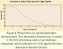
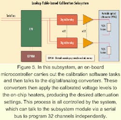
Lookup table-based calibration uses test data generated for a VOA to calibrate and achieve highly accurate attenuation settings. Typical attenuation characteristics are shown in Figure 4. The attenuation characteristic is stored in the form of a lookup table on an electronic subsystem, which calibrates the VOA against the ideal attenuation transfer function. An example of an electronic lookup table-based subsystem is shown in Figure 5. In this subsystem, an on-board microcontroller, the CPU, carries out the calibration software tasks and then talks to the digital/analog (D/A) converters. These converters then apply the calibrated voltage levels to the on-chip heaters, producing the desired attenuation settings. This process is all controlled by the system, which can talk to the subsystem module via a serial bus to program 32 channels independently. This approach facilitates highly integrated reconfigurable multichannel power equalization.While the lookup table offers calibrated attenuation setpoints, it cannot calibrate against dynamic events and effects, which may cause the attenuation setpoint to drift. The lookup table also puts greater demands on the VOA and control-system performance. For example, temperature effects on optical performance have to be well understood and accounted for in the component design. Changes in polarization causing additional optical loss through the VOA have to be minimized, or the device has to be very polarization-dependent-loss insensitive.
Mechanical-based VOAs tend to be implemented in control loops. A small percentage of the output optical signal is tapped off and fed to a control system, which automatically adjusts the attenuation setting. However, these systems tend to have very slow response times, since they are essentially offsetting relatively long-term consequences such as temperature effects and mechanical wearout. The control systems are not designed to dynamically compensate for faster polarization changes due to mechanical shocks on the fiber.
A new approach to optical power-level setting and maintenance is to design a VOA subsystem that can respond fast enough to the most likely effects causing unwanted changes in output optical power levels. In this subsystem, a PIN photodetector is used to actively monitor the output optical power levels. The on-board microcontroller reads the digital output from the analog/digital (A/D) converter and mathematically compensates for non-ideal output optical power. It programs new attenuation levels via the D/A converter and buffer amplifier.
Since the PLC VOA is essentially an analog component, the system resolution is a function of the accuracy and resolution of the electronic components employed. An attenuation resolution of 0.1 dB can be achieved by employing 8-bit A/D and D/A converters. The 10-bit and 12-bit converters are available at relatively low cost, so significantly better resolution is achievable. Loop-response times of less than 5 msec are possible.
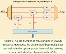
One of the main applications driving multichannel VOA implementation is the technology's use in optical add/drop multiplexers (OADMs). As the number of wavelengths in metro networks increases, so does the requirement to maintain the optical power levels of a growing number of individual channels in the OADM. The optical power levels can be monitored and controlled using VOAs (see Figure 6).
As DWDM wavelength densities head toward 96 and above, there is an increasing requirement to produce higher levels of integration in the VOA function. Since PLC VOAs are planar-IC-based, it is possible to significantly increase the number of VOA channels per silicon PLC without taking up a lot more board space.
The PLC approach also presents the opportunity to integrate the arrayed-waveguide-grating multiplexer onto the same optical IC as the VOAs. Further integration could place waveguide-based switches onto the same IC. This system-on-a-chip methodology, which has revolutionized the semiconductor industry and offered multiple benefits to electronic systems vendors, is within reach for optical-network equipment manufacturers. As the number of wavelengths in DWDM systems increases, PLC VOAs combined with highly integrated control subsystems offer a scalable path to realizing these high-density systems.
Dr. Vivek Tandon is the director of business development and Jim McGonigal is a product manager at Kymata Ltd. (Livingston, UK).
