AM systems tolerate increased reflectance
AM systems tolerate increased reflectance
Fiber-optic links that are 5- to 20-kilometers long and that contain as many as 16 passive devices continue to perform adequately despite multiple component reflectances
Barbara L. birrell
3m telecom systems division
Amplitude-modulated vestigial sideband systems can tolerate more reflection than was previously believed because of passive fiber-optic components. Scientists at 3M Telecom Systems Division and AT&T Cable Network Systems, in a joint study, have shown that an average reflectance of -55 decibels is acceptable for all AM-VSB systems. According to their study, stricter requirements for component (splice and connector) reflectance provide little, if any, improvement to the system. In fact, larger reflections were demonstrated to be acceptable in most analog systems.
Reflections occur in a fiber-optic link when the transmitted signal strikes a fiber-to-fiber interface in connectors and mechanical splices. At the interface, a small percentage of the signal is reflected back toward the transmitting laser. The percentage of the signal reflected at the interface is known as the reflectance of the interface. Important reflectance parameters that should be considered include the average reflectance of mechanical splices and gelled connectors at the thermal extremes of typical storage environments, and of PC-type and angled-polish fiber-optic connectors.
When stored in aerial closures, mechanical splices and gelled connectors typically exhibit an average reflectance as high as -45 dB with flat cleaves and -63 dB with angled cleaves. In underground closures, mechanical splices and gelled connectors typically exhibit an average reflectance as high as -50 and -68 dB with flat cleaves and angled cleaves, respectively. PC-polish connectors have a typical reflectance of -54 dB, whereas angled polish connectors have a typical reflectance of -75 dB. These PC-polish connectors can produce a -14 dB reflectance when there is no contact between the fiber endfaces. The typical reflectances cited for flat PC-polished connectors do not account for this effect.
Rayleigh backscatter
The fiber itself also contributes reflections to the system. These reflections occur when the transmitted signal strikes impurities in the fiber. The total reflection from fiber impurities along the fiber length, reduced by the loss of the fiber, is known as the Rayleigh backscatter of the link; the total reflectance approaches -31 dB as the fiber length approaches 20 km.
Rayleigh backscatter establishes the minimum reflection in a link as measured at the laser. The reflection of a component as measured at the laser is the reflectance of that component reduced by the loss between the component and the laser. The total reflection of a link is the sum of the Rayleigh backscatter of the fiber and the reflection of the components in the link as measured at the laser. In addition to splices and connectors, such system components as lasers, couplers and detectors can also contribute reflectance to the system.
Reflection into the laser is not a concern in today`s transmission systems because optical isolators prevent the reflected light from interfering with the source. However, reflected light may be rereflected toward the detector. Double reflections occur when a small portion of the light that is first reflected back toward the source is rereflected as it strikes other reflective surfaces, including connectors, mechanical splices or fiber impurities. Double reflections occur between every pair of reflective components as well as between every reflective component and the fiber Rayleigh backscatter, and within the fiber alone as double-Rayleigh backscatter.
The single and double-Rayleigh backscatter of the fiber is as a function of the fiber length. Double-Rayleigh backscatter can range from approximately -75 dB for a 5-km link to -65 dB for a 20-km link. A pair of -50 dB reflectance splices or connectors with minimal loss between them would have a double reflection of approximately -100 dB. These double reflections travel toward the detector as signal noise. As a result, double reflections might degrade video quality; therefore, they are a concern when AM-VSB systems are being designed. To predict how much degradation the components may cause, a calculation must be made on how much the components contribute to the total double reflection of the system.
This calculation must take into account that every pair of components creates a double reflection cavity. A link with four components, for instance, would invoke a total of six double reflection cavities and thus six double reflections. The sum of all the double reflections that result from the components is known as the component interferometric reflectance.
Given a number of reflective components with a distribution in reflectances and an average reflectance, the component interferometric reflectance would attain a maximum value when all the reflectances are equal in magnitude and spacing. Therefore, a worst-case prediction of the system`s total double reflection is made by using the average reflectance of the components instead of the actual distribution of the reflectances.
Double reflectance
Double-Rayleigh backscatter establishes an inherent double reflectance level in the system. No matter how low passive component reflections are, the total system double reflectance will never be lower than this inherent level. Because of the reflections inherent in the fiber, if reflections from passive components are reduced to a level where they no longer contribute substantially to the total system double reflectance, they cannot impact system performance.
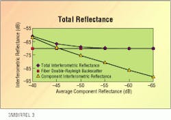
For example, consider a 10-kilometer fiber-optic link that contains eight passive components. The total interferometric reflectance is defined as the double reflection resulting from the eight components and the fiber double-Rayleigh backscatter in the link.
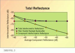
The 3M/AT&T study shows that the total interferometric reflectance approaches the level of double-Rayleigh backscatter as the average component reflectance decreases. That is, as the average component reflectance decreases from -40 dB and reaches almost -55 dB, the components no longer contribute substantially to the total system reflectance. Above -65 dB, the total interferometric reflectance settles at approximately -70.4 dB, which is the value of the fiber`s double-Rayleigh backscatter.
The total system reflectance can be reduced to the level of the fiber`s double-Rayleigh backscatter by reducing the average reflectance of the components to -55 dB. Signal quality will not be improved by reducing the average reflectance below -55 dB.
Signal degradation
Although analog systems do not fail catastrophically because of reflections, signal quality can degrade. Whereas analog system composite-triple-beat and composite-second-order distortions do not degrade because of interferometric reflectance, high levels of interferometric reflectance will decrease the carrier-to-noise ratio of the signal. Nevertheless, this degradation can be avoided by ensuring the number of components or the average reflectance of the components is low enough so their contribution to the total system interferometric reflectance becomes insignificant.
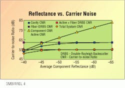
The total interferometric reflectance, number of channels and spectral width of the laser establish the cavity carrier-to-noise ratio of the system. In any case, the system carrier-to-noise ratio cannot exceed the cavity carrier-to-noise ratio. The study reveals, for example, that a -70-dB total interferometric reflectance typically converts to a 62-dB cavity carrier-to-noise ratio for an 80-channel system with a 2500-megahert¥spectral width laser. Beyond that, the active components (for example, lasers and detectors) further limit the maximum potential carrier-to-noise ratio of the system.
In addition, the study shows that an 80-channel system that has a low-noise laser and detector and 1 milliwatt of received power can have an active carrier-to-noise ratio as high as 56 dB. The cavity carrier-to-noise ratio and active carrier-to-noise ratio then combine to determine the system carrier-to-noise ratio. In this application, the component interferometric reflectance, fiber double-Rayleigh backscatter and the total interferometric reflectance are all converted into carrier-to-noise ratio values.
As a result, the cavity carrier-to-noise ratio increases from 55 dB and approaches the fiber carrier-to-noise ratio value (62 dB) because of the fiber`s double-Rayleigh backscatter when the average component reflectance goes from -40 dB to -55 dB. The active carrier-to-noise ratio is a constant 56 dB.
The system carrier-to-noise ratio ranges from 52 dB when the average component reflectance is -40 dB to the 55-dB limit established by the combination of the active components and the fiber double-Rayleigh backscatter. This interaction shifts the point where the component reflectances begin to degrade the system from an average reflectance of -55 dB to an average reflectance of approximately -50 dB.
If this study model is expanded to include links 5 to 20 km in length, that have as many as 16 components, an average reflectance value of -55 dB consistently ensures the component reflectances do not markedly degrade the system. This average reflectance is easily obtained through the use of the latest mechanical splices, angled cleaver adapters and cleavers. q
Barbara Birrell is senior physicist for the 3M Telecom Systems Division in Austin, TX.Carrier-to-noise ratio is the ratio of the carrier peak to the noise floor in the system. The ratio can be reduced through a reduction of throughput power or through an increase in total noise. Reflections that result from components and fiber and noise caused by active components combine to raise the noise floor of the system. This increment reduces the system carrier-to-noise ratio.


