Tunable optics with smart electronics enable affordable agile optical networks

While cost and complexity may seem to be significant problems, new technology promises to bring the benefits of tunability to several points in the network.
Mark Lourie
Aegis Semiconductor
During the telecommunications market downturn, plans for optical network equipment designs involving tunable optics were put on hold like many other new technologies. Yet tunable optics is again being designed into architectures today. The reason for this renewed interest is that tunable optics promises to reduce total cost of ownership in optical networks.
The case for tunable optics
Network operators agree that tunable optics can reduce the cost of sparing. Most network operators determine the level of sparing according to a mean-time-to-failure (MTTF) figure specified for each line card by the equipment vendor. In the case of DWDM transponder line cards, it is common practice for a network operator to stock a spare line card for every deployed DWDM wavelength. The cost can be shared regionally over a number of network elements but nevertheless remains an inevitable point of contention during contract negotiation. In fact, it is not uncommon for the equipment vendor to agree to bear the cost of sparing in the heat of a competitive bid. In that situation, the equipment vendor bears the cost of static optics two times: as raw inventory, usually of spare DWDM lasers, and as finished goods to support the network operator. Thus, the business case for tunable DWDM transponders is self-evident: the cost of sparing comes down by a factor proportional to the number of wavelengths provisioned.
But tunability can benefit other aspects of optical networking. For example, network planners know from experience that optical equipment must follow strict engineering rules to function properly. Such engineering rules can be quite restrictive, especially when considering upgrade scenarios. As an example, DWDM routes are designed very carefully by taking fiber type, distance, and bit rate into account to ensure that the proper dispersion compensation modules are selected for the right repeater site (optical amplifier). If that same route requires changing the mix of 2.5- and 10-Gbit/sec wavelengths, the implication may be a laborious upgrade involving not only the transponder line cards at the end terminals, but the repeaters in between as well. This example is one reason why tunable dispersion compensators have come on the market: to try to fill the need for more flexible design rules.
Meanwhile, optical networking equipment vendors search for performance advantages in order to claim a competitive edge in the form of lower cost per bit per kilometer of transmission. As a result, systems engineers must fulfill increasingly stringent performance requirements. One option is to demand higher-performing optical components with ever-tighter tolerances from their component vendors. Another approach is to move to adaptive subsystems, where tunable optical functions are constantly monitored and adjusted via algorithm. Spectral monitors, variable optical attenuators, gain tilters, and dynamic gain equalizers represent examples of subsystems to which tunable functionality may be applied.
Finally, network operators have deployed massive numbers of electrical digital crossconnects and SONET add/drop multiplexers. One essential factor in these systems' success is the simple fact that they are fully reconfigurable and entirely non-blocking. In other words, any one port can be switched to any other port at any time without affecting any of the other connections in place. Network operators thus are assured that the entire bandwidth of that digital crossconnect will be available, no matter how the traffic patterns may evolve. Optical networking engineers have looked for technology to provide the same switching functionality at the wavelength level. A wide range of components has emerged to compete in this market, including micro-mechanical mirrors, liquid crystals, and tunable filters.
Tunable optics challenges
With all the potential that tunable optics offers, one may wonder why it isn't already more widely designed into today's optical networks. The reality is that many tunable components struggle to match the cost and size of their static and already commoditized counterparts. A debate often heard at conferences revolves around how much of a price premium tunability should command. The answer almost always seems to be "not much."
One reason for the bigger price tag is the difficulty in making adequate electrical contact to the optical device without compromising optical alignment. In addition, the electrical contacts almost always must be routed perpendicularly to the optical axis so that the components can be soldered onto a printed circuit board and the fiber pigtail routed parallel to that board. These seemingly mundane requirements add complexity when selecting a packaging platform to house a tunable component.
These packaging challenges also can turn into testing challenges. In most cases, the optical element is mounted and wire bonded in a package before proceeding to fiber attachment. Additional complexity is encountered at the fiber alignment bench if the optical device must be electrically connected to optimize fiber alignment and attachment. If the fiber attachment takes too long or if it fails altogether, material and labor are wasted.
Tunability itself also raises a set of unique concerns that conservative buyers will want to insure are adequately addressed from all aspects of operation, administration, maintenance, and provisioning (OAM&P) of the optical network.
Emerging trends
Several trends suggest that the most successful applications of tunable optics in the telecommunications market will marry low-cost core optical technology with smart electronics to keep the performance adequate. The following three examples illustrate this premise in action.
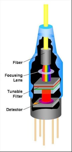
As DWDM took central stage in optical transport, network engineers looked for a way to integrate some spectrum analysis capability into DWDM network elements to conveniently track the behavior of each wavelength. Almost overnight, the $70,000 laboratory-grade optical spectrum analyzer had a $15,000 cousin, called an "optical channel monitor" (OCM), that was small enough to fit on a line card. From a technology standpoint, this was the first step in the simplification of optics from rotating bulk gratings to fixed gratings, which were combined with a 512-element detector array borrowed from the field of NIR spectroscopy. Since then, OCM optics has become even simpler by adopting tunable filters with single element detectors (see Figure 1). The simplification of the optics has come concurrently with an increase in the intelligence of the electronics. Data processing algorithms such as peak detection and deconvolution have become increasingly sophisticated. The net result over the past several years is stable OCM performance as prices have come down by an order of magnitude.
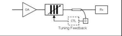
Another example is wavelength multiplexing or demultiplexing filters. The conventional wisdom is that thin film (TF) filtering is the technology of choice for low-channel-count add/drop multiplexing when compared to arrayed waveguides or fibber Bragg gratings. The challenge in manufacturing TF filters lies in the fact that the square transmission profile must center on the ITU grid with relatively high precision during the wafer manufacturing process. Such high precision is necessary because DWDM designers must account for drifts in the laser transmission as well as the trunking effects of filters cascaded in series around a DWDM ring, especially as the filters might drift independently depending on the temperatures at each add/drop location around the ring. The TF filter designer therefore strives for filter characteristics with "squarer tops" and "steeper slopes" while manufacturing engineers strive to properly target a filter type for each of the ITU grid centers. Tunable filters can alleviate the stringent requirements found in fixed filter requirements, since they can be actively tuned. External feedback and control (Figure 2) to re-center the filter to the transmitter's signal eliminates all issues of laser and filter targeting and drift over temperature and lifetime. This demonstrates that optical complexity can be reduced to save cost while leveraging the electronics in the control loop to provide adequate performance.
A significant amount of R&D has been spent to create a tunable chromatic dispersion compensator (TCDC). Many of the early solutions were all optical and based on elegant non-linear optics theory. However, the general consensus seemed to be that when turned into products these all-optical solutions lacked enough performance to justify their high cost. It is now clear that dynamic electronic dispersion compensation (EDC) will be the technology of choice because this electronic solution can achieve orders of magnitude more of correction per dollar in comparison to all-optical approaches. In the future, new low-cost optical designs for TCDC may leverage eye diagram parameters generated by the EDC to take TCDC performance to yet another level.
Conclusion
Tunability in optical networks is not a question of "if" but a question of "when." And as would be expected, cost is a key factor. At first glance, it may seem that tunability adds more complexity to the optics and increases manufacturing costs. However, this does not have to be the case. Instead, a trend is emerging where simpler and lower cost optics are married with even more intelligent electronics to provide the right tunable optical solution at the right cost for each application. With this approach, the intrinsic benefits of tunability can be deployed in the optical network.
Mark Lourie is director of product management at Aegis Semiconductor (Woburn, MA); www.aegis-semi.com