How to test laser-based premises networks
With higher speeds demanding a switch from LED light sources, new test regimes have become essential for LANs.
Thomas R. Jordal, Fluke Networks
The rapid deployment of performance-dependent protocols such as Gigabit Ethernet is spurring the growth of fiber-based LANs to handle the ever-increasing bandwidth requirements for faster data transmission. Multimode optical fibers, fibers designed specifically for Gigabit Ethernet, and singlemode optical fibers are being deployed as the high-speed transmission media in the premises market. Consequently, to achieve faster data rates, the optical signals are being launched by laser light sources as opposed to light-emitting-diode (LED) light sources.
Because lasers are now being used in both multimode and singlemode, testing requirements have changed. Technicians in stalling or maintaining fiber-optic networks must learn new fiber test procedures and understand how to choose the proper test equipment to obtain accurate test results.
Exploring the fundamental differences between lasers and LED light sources and the differences between singlemode and multimode fiber will clarify why high-performance, high-speed optical-fiber networks require properly matched test equipment.
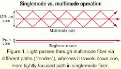
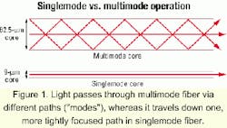
Lasers launch light in very-high-powered, concentrated beams while LEDs emit diffuse beams at typically lower power. Lasers are also capable of a much faster pulse rate than LEDs, which is one of the main reasons they are preferred for high-speed networks. With singlemode links, conventional Fabry-Perot lasers are being used, while the new vertical-cavity surface-emitting lasers (VCSELs) are being installed for short-wavelength Gigabit Ethernet over mulitmode fiber.In a singlemode fiber, the solitary mode is called the "fundamental mode" or "lowest-order mode" and it travels down the center of the core. By contrast, multimode fiber contains many modes. Those that are confined to the center of the fiber core are called "lower-order modes" while those that travel near the exterior of the fiber core are noted as "higher-order modes." This distinction becomes important for loss testing, because higher-order modes are more susceptible to loss due to bending of the fiber.
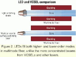
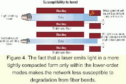
This is also where a difference between lasers and LEDs comes into play. Because a laser concentrates the light energy near the center of the fiber, only the lower-order modes are excited when used in a multimode fiber. However, an LED yields what is called an overfilled launch because it completely fills the fiber and excites all modes, both lower order and higher order (see Figure 2).
Consequently, a multimode fiber using an LED light source is more susceptible to loss than a multimode fiber using, for example, a VCSEL source. This is yet another reason why a VCSEL source is chosen for high-speed network applications.
Now that we understand some of the fundamental differences between light sources and fiber types, let's look at the proper means of testing laser-based fiber networks.
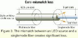
Singlemode fiber uses lasers for optical transmission and, consequently, lasers should be used for testing. But what if you already have an LED source at 1,300 nm? Can you use it to test the singlemode fiber?Well, the answer is you might be able to, but this approach is highly discouraged because of some severe limitations imposed by such a test method. First, you will have an incredible amount of loss at the fiber interface between the source (which uses a 62.5-micron multimode internal fiber) and the network fiber (which is 9-micron singlemode). This core-mismatch loss will run about -20 dB (see Figure 3). Consequently, you will be limited in the distance over which you can actually test.
But more importantly, if you are measuring loss at only 1,300 nm, you are missing an important measurement parameter for singlemode-and that is determining what the loss is at 1,550 nm. When testing singlemode you should properly characterize the link under test for any wavelength at which it might operate. If you test singlemode with an LED, you will still have only an assessment of the fiber link at 1,300 nm. But because singlemode networks may use 1,550 nm for optical transmission sometime in their lifetime, it is important to test at both wavelengths.
It is especially important to test at 1,550 nm because the 1,550-nm wavelength is much more susceptible to bending losses than is the 1,310-nm wavelength (see Table). If you install a fiber network and test only at 1,310 nm, you could still have a serious bend-radius violation somewhere in the fiber and not be able to pick it up at 1,310 nm. If the network ever runs at 1,550 nm, it could fail because the 1,550-nm wavelength is much more sensitive to bending losses.
Tests on 11.5-mm and 18-mm mandrels are severe. They are not intended to simulate actual usage conditions, but rather to demonstrate the wavelength-dependent loss at unintentional sharp bends such as might be encountered in installation.
All of the above indicate why it is so important to follow proper testing practices when testing singlemode fiber. The bottom line is that you should always test a singlemode laser-based network with lasers and test at both 1,310-nm and 1,550-nm wavelengths.
For laser-based fiber networks where multimode fiber is being used to run Gigabit Ethernet, the allowable loss budgets are much tighter than with 10 or 100 Mbits/sec. Thus, the test method and accuracy are correspondingly more critical. With Gigabit Ethernet, VCSELs are the sources used for optical transmission at 850 nm and conventional Fabry-Perot lasers at 1,310 nm (primarily because VCSELs at 1,310 nm are not commercially available yet).
It is important that you test your multimode Gigabit Ethernet link with the same type of sources it uses, so lasers are the best choice.This is because an LED transmits a wide and diffuse array of light energy that fills the multimode fiber and has far more higher-order modes than will a laser. These higher-order modes are more susceptible to bending loss. Also, if there is any misalignment at the fiber-to-fiber connection (there is always some alignment variation), the receiving fiber will not capture all the light energy. By contrast, a concentrated beam of laser light is not nearly as sensitive to misalignment between fibers (see Figure 4).
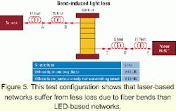
Consequently, the LED test will exhibit much greater loss (due to both bending loss and connector loss) than will the VCSEL test (see Figure 5). It follows then that the LED test could very likely give a fail result (especially with the tight loss limits imposed by the Gigabit Ethernet standard) when the link is really okay. A fail result could mean spending valuable time looking for a problem that does not exist. This same argument applies to testing Gigabit Ethernet over multimode fiber at 1,310 nm.The deployment of singlemode fiber and multimode fiber in gigabit-speed applications such as Gigabit Ethernet is on the rise. These high-speed networks use a variety of lasers as optical transmission sources.
By certifying a network's fiber infrastructure with the identical types of sources found in switches and other network equipment in use, cabling professionals and network owners can be certain that the fiber plant will endure the demands of the network equipment.
Thomas R. Jordal is fiber test manager for Fluke Networks Inc. (Everett, WA).
