Optical smarts without the legacy baggage

With intelligent monitoring and management, digital-wrapper technology provides a standards-based approach for managing optical transport networks.
DR. NEAR MARGALIT
and KENDALL HOLBACK, Zaffire Inc.
As carriers continue deploying new DWDM technologies, it is critical to manage their evolving fiber-optic networks in an efficient, cost-effective manner. That poses a considerable challenge for today's service provider-while various DWDM technologies exist, there is no widely available standards-based method for managing an optical transport network (OTN). This situation is about to change with the advent of a new technology called digital wrapper.
Digital-wrapper technology, a standards-based optical-network-management solution, intelligently monitors and manages multiple wavelengths in OTNs with single-wavelength granularity. The advanced technology encapsulates the native signal without disrupting the bit rate, format, or timing of the client signal, thus enabling the optical network to support transmission of virtually any client protocol. This means network operators now have an intelligent, standards-based method for managing DWDM optical transport networks.
To date, carriers have deployed SONET/SDH technology as the accepted method for managing metropolitan transport networks. Unfortunately, SONET/SDH is optimized for a relatively simple transport network using single-wavelength transmission. In a SONET network, all information is manipulated in the electrical format (bits).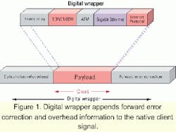
Today, advanced OTNs based on DWDM are emerging that include optical network elements such as transponders, optical add/drop multiplexers, in-line erbium-doped fiber amplifiers (EDFAs), optical multiplexers/demultiplexers, optical spectrum analyzers, and optical switches. The introduction of these new technologies has actually created new sublayers within the optical network. The ability to perform monitoring functions, such as fault isolation between these sublayers, has become a requirement for carriers.
The SONET/SDH protocol was not designed with these optical-network elements in mind and lacks the functions required to effectively manage them. In addition, SONET/SDH has many other limitations, such as the restriction of a maximum of 16 network nodes per ring. Furthermore, the SONET/SDH framing format is optimized to carry voice traffic using strictly defined time-division multiplexing (TDM) timeslots. At the same time, SONET/SDH offers many benefits for TDM-based service delivery and has played a crucial role in service-provider metropolitan transport networks. While SONET/SDH will continue to be deployed by carriers on a large scale, it has a well-defined place in the network.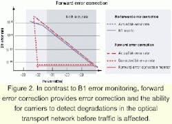
Given these limitations and the fact that data traffic will increasingly consume the vast majority of network bandwidth, SONET is ill-suited to the meet the demands of the current metro optical transport networks, not to mention the even higher-capacity optical networks of tomorrow. Rather, forward-thinking carriers need solutions that intelligently monitor and manage multiple wavelengths in the optical transport network. With single-wavelength granularity. The emergence of advanced optical DWDM networks, while co-existing with SONET, will ultimately drive the operational innovations in the carrier networks of tomorrow.
Digital wrapper provides the robust, carrier-class features necessary for management and intelligence in the optical domain. With digital-wrapper technology, each wavelength, or optical channel, can be monitored and managed nonintrusively by placing a digital envelope, or "wrapper," around the optical channel itself. A section of digital overhead bandwidth is added to the client signal before it is sent over the optical network. By doing this, management and control information about the client signal, and the optical transport network itself, can be transmitted with the client signal through the network.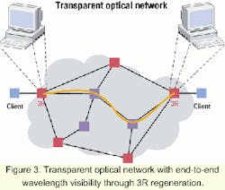
One major advantage to digital-wrapper technology is its compatibility with all existing network communications protocols. This backward compatibility is possible because digital wrapper operates separately from the client signal being transported. Because digital wrapper encapsulates the native signal without disrupting the bit-rate, format, or timing of the signal, the optical network can support transmission of virtually any client protocol. This makes digital wrapper, and therefore the OTN, protocol-agnostic. For example, in a digital-wrapper-enabled network, optical-channel-overhead (OCh-OH) information is appended to the outside of an OC-48 (2.5 Gbits/sec) SONET/SDH signal such that the OC-48 client signal is always operating at its intended data rate. This holds true for any protocol that interfaces to the optical transport network.
Transponders on optical transport systems can directly support client-side interfaces such as Gigabit Ethernet (GbE), ATM, frame relay, and Internet Protocol, or be bit-rate independent, supporting protocols such as Fibre Channel, Escon, or Ficon.
Bit-rate-independent, protocol-transparent tributary interfaces with clock recovery can support any bit stream operating from 100 Mbits/sec through 10 Gbits/sec across the optical transport network. With digital wrapper, the serial data rate of the optical channel is actually increased to transport the client signal plus the digital-wrapper overhead that has been added (see Figure 1).
Advanced optical systems that support protection can increase efficiency by intelligently protecting gigabits of traffic at the optical layer. This feature can simplify the carrier network by subsuming protection functions that exist separately in other in protocols at various layers of the network, such as SONET, ATM, and transmission control protocol. Optical protection signaling and management functions can be provided via digital wrapper in the OCh-OH. In addition, protocols that are natively unprotected can now be protected in the optical domain.
In addition to supporting OCh-OH information, digital wrapper also makes use of some well-known techniques to provide an innovative method for performance monitoring in the optical domain. Along with the OCh-OH information, digital wrapper inserts an algorithm that is highly effective at detecting and correcting any errors encountered across an optical link. Forward error correction (FEC) is an established method used today in most compact disc players, data storage devices, and undersea fiber-optic systems for correcting errors in a bit stream.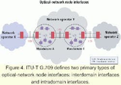
In contrast to the traditional BIP-8 error-monitoring method used in SONET (B1, B2 bytes), systems that employ FEC can report detected error rates, giving service providers visibility to optical performance degradation before the customer ever sees a change in their contracted service level. Figure 2 shows the comparison between FEC and B1 error monitoring.
With the B1 algorithm, the actual bit-error rate (BER) is the same BER that is reported to the network operator. With the FEC algorithm, the network operators have visibility to both the actual BER on the optical channel as well as the corrected BER that FEC provides. Error rates can be reported in SONET-like formats that are familiar to network operators, such as errored seconds, severely errored seconds, severely errored framing seconds and unavailable seconds.
When coupled with an intelligent operating system, network operators can define and set separate BER thresholds for each optical channel in a DWDM optical transport network. Systems that intelligently combine FEC technology with these features enable service providers to guarantee, measure, and deliver differentiated performance levels for optical services.
It is well known that reducing the number of optical-electrical-optical (OEO) conversions in the optical network reduces operating complexity and capital costs while increasing reliability and efficiency. An OEO conversion is characterized by "3R" regeneration of the optical signal: reshaping, regeneration/amplification, and retiming. Also, 2R regeneration (reshaping and regenerating/amplifying) has been made possible by the EDFA and is a primary factor contributing to the success of DWDM technology, because it allows simultaneous regeneration of many optical signals without a full OEO conversion.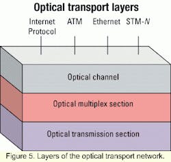
Reducing the number of OEO conversions in the network is characterized as increasing the transparency of the optical network. This notion of a completely "transparent" optical network has generated a lot of interest in the industry. But without converting the optical signals into digital format there is no way to process management information about the signal. Therefore, in a totally transparent optical network, management information about the network remains invisible. Since completely transparent optical networks are difficult to manage, it is highly unlikely that a service provider would ever deploy them on a large scale.
In contrast to a transparent OTN, in an opaque OTN, every node performs full 3R functionality on the optical signals it carries, regardless of whether it is the destination node or not. Obviously, this can be very inefficient, detracting from many of the benefits of optical networking. While completely transparent optical networks are not practical and opaque optical networks are costly and inefficient, the ideal optical network should provide enough visibility for effective network management while minimizing the number of OEO conversions.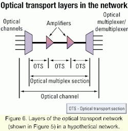
In a digital-wrapper-enabled network, 3R regeneration is performed at the ingress of the optical network, when the client signal is mapped into a digital wrapper and converted to an optical channel. During transport through the network, the channel remains in optical form until it reaches its destination, where it is converted back to electrical form and 3R regeneration is performed. This type of architecture provides per-wavelength visibility for network management where needed, at either end of the optical-channel trail, while minimizing the number of OEO conversions through the network (see Figure 3).
Today, digital wrapper is being implemented by a few technology leaders who wish to leverage its many benefits within a given network domain. However, in the not-too-distant future, these features must be supported across multiple administrative domains and between systems from different vendors that must inter operate. These administrative OTN do mains may be designated by the network operator or by the equipment vendor. Carriers are now leasing wavelength services to other carrier-customers and must be able to hand off optical channels between digital-wrapper-enabled and non-digital-wrapper-enabled networks under different administrative control.
Soon, optical customer premise equipment for high-bandwidth enterprise customers will also need to support digital wrapper. Even within a single-carrier network, operators must be able to provision and manage wavelengths end-to-end, across multiple vendor subnetworks. The 3R regeneration points in the network provide a window of visibility through digital wrapper, becoming natural demarcation points between different administrative network domains.
Just as an accepted standard defining SONET/SDH helped drive the broad adoption of that protocol, a standard defining digital wrapper will drive its adoption in the optical transport network. These standards are the result of collaboration among optical networking industry leaders to ensure interoperability between different vendor systems. The International Telecommunications Union- Telecommunications (ITU-T) standards body has recently frozen a draft recommendation, ITU-T G.709 network node interface for the OTN, outlining the details of the digital-wrapper implementation in the context of interconnecting optical transport networks.
The ITU-T G.709 identifies optical-network node interface (ONNI) interconnection points as being interdomain interfaces (IrDIs). IrDIs are the boundaries between OTNs of different administrative domains. The administrative domains may be that of multiple network operators and/or equipment vendors.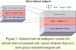
A hypothetical example of an IrDI would be the ONNI between two carriers: Carrier X and Carrier Y. At this interconnection, the two carriers may hand off DWDM optical channels. Note that another example of an IrDI is the interface between two vendor DWDM systems inside a single carrier's OTN (see Figure 4).
Intradomain interfaces (IaDI) are interconnections within a given administrative domain. Examples of IaDI's could be any interface within a single vendor subnetwork, which may or may not extend to include the entire carrier OTN. Since IrDIs interconnect multiple administrative domains, they are the subjects of standardization in the G.709 draft. IaDIs are not the subject of the G.709 standardization, beyond supporting some of the features necessary for network management.
Carriers should be very aware of a vendor's ability to support the features necessary for OTN management within their own subnetwork, or IaDI. A closer look at the layers of the OTN and the definition of the ONNI is required and will demonstrate the need for a clean mapping of functionality from the internal interfaces (IaDIs) to external interfaces (IrDIs).
Within the OTN, there are three primary layers defined: the optical-channel (OCh) layer, the optical multiplex section layer (OMS), and the optical transmission section layer (OTS) (see Figure 5).
Client signals are mapped from a digital format into an optical format and into an OCh. Several OChs are optically multiplexed together to create an OMS. The OMS is transported optically over a span of fiber-optic cable that constitutes the OTS. Figure 6 illustrates these layers as they might exist in a simplified OTN.
The structure and layers of the OTN closely parallel the path, line, and section sublayers of SONET. Although the G.709 standard extends into the layers below the optical channel (OMS and OTS layers), digital wrapper exists primarily at the OCh layer. It is important to note that the G.709 standard allows for a scenario in which there are no OMS or OTS layers-essentially a single-channel, non-DWDM network. This is made possible by the optical physical section 0 (OPS0) layer, which allows the transport of a single optical channel over fiber-optic cable. The OSP0 allows carriers to benefit from the same features and functionality of digital wrapper across both DWDM and non-DWDM OTNs.
Although the optical channel was simply described earlier as the client signal with some overhead, the OCh is actually divided into three substructures: the optical-channel transport unit (OTU), the optical-channel data unit (ODU), and the optical-channel payload unit (OPU). Each has its own functions and associated overhead (see Figure 7).
There are many important features enabled at the OPU, ODU, and OTU optical-channel sublayers. One such feature that enables optical performance monitoring as well as optical demarcation is tandem connection monitoring (TCM). TCM operates at the ODU sublayer of the optical channel. Because it allows an optical channel to be managed and monitored through multiple OTNs, TCM is a feature of digital wrapper that truly enables wavelength services.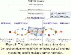
The following scenario illustrates TCM in a typical wavelength service offering through metro and long-haul service-provider OTNs. The ODU path of a wavelength service can be monitored from optical Customer A in San Francisco, through a metro-optical service-provider network, to a long-haul optical service provider for transport across the country, back to metro-optical service provider in New York, and finally back to Customer A in New York City (see Figure 8).
As the ODU connection is made from the customer network to the metro-service-provider network in San Francisco, the TCM1 field is populated and is stacked onto the path monitoring (PM) field in the ODU-OH. As the ODU connection traverses the long-haul carrier network, the TCM2 field is populated, stacked on top of TCM1, and designated top of stack (TOS). When the ODU connection reaches the metro-service-provider-to-service-provider network in New York City, TCM2 is removed and TCM1 is again designated TOS. As the ODU connection is completed to Customer A in New York City, TCM1 is removed and the original PM field is left to convey the end-to-end path-monitoring information.
Up to seven tandem ODU connections can be monitored through the nesting capability afforded by the path-layer monitoring in digital wrapper. In each connection BER, performance, trail trace, and defects can be monitored. As should be evident, this capability allows for true connection monitoring in the optical domain, across multiple optical networks, regardless of optical-equipment manufacturer or operator.
A quick study of the G.709 standard illustrates how digital wrapper succeeds at providing SONET-like functionality for optical transport networks. OTS, OMS, and OCh network layers enable optical-network architectures that can truly leverage the efficiencies of the optical networking. While equipment vendors have the freedom to implement proprietary versions of digital wrapper within their own networks, they must support the requisite section layer functionality in order to pass that information across an ONNI. Proprietary solutions for optical-network management that vary wildly from the G.709 framework will add operating complexity to optical systems and ultimately increase operating costs for service providers.
The G.709 standard facilitates vendor interoperability and provides a means for carriers to make high-bandwidth, DWDM optical interconnections. Highly transparent optical carrier networks can now be interconnected optically, with clear and concise demarcation points and a system that supports fault isolation. Interconnections can be made that scale from single-wavelength granularity up to multiwavelength, multiterabit capacity.
Equipment vendors who wish to offer the most robust, carrier-class optical transport systems should be designing toward support of digital wrapper today. Systems vendors who are designing architectures with this foresight and working closely with leading chip vendors will be well positioned to quickly implement the features afforded by this technology. System vendors that are not, face the risk of having to re-architect everything from hardware imple mentations to net work-management-system functionality in order to support digital wrapper. Carriers currently evaluating optical transport systems should seriously consider these facts before choosing a vendor.
Digital wrapper is backwards compatible with existing electrical and optical protocols. Any client signal can be transported optically over a digital-wrapper-enabled network. Non-DWDM optical networks supporting SONET and GbE-over-fiber can coexist with digital wrapper on the same physical fiber infrastructure. Carriers can take advantage of digital wrapper to provide error monitoring, error correction, and protection for protocols and services that don't natively support these features.
FEC in digital wrapper allows carriers to provide differentiated service-level agreements on any protocol or service. TCM at the ODU layer enables end-to-end optical-channel monitoring and management, through several administrative domains or networks. Features such as general communication channels and trail trace identifiers can be used with traffic-engineering protocols such as Multiprotocol Label Switching to enable rapid, or even dynamic provisioning of optical channels.
Digital wrapper provides the robust management features necessary for high-bandwidth optical transport networks. Just as SONET allowed carriers to break the bandwidth bottleneck of T3 (45-Mbit/sec) connections in the 1980s, digital wrapper allows carriers to break the gigabit bandwidth bottlenecks of today. Carriers can now harness the rapid advances in optical transmission technology into deployable and manageable solutions.
Dr. Near Margalit is chairman and chief technology officer and Kendall Holback is a technical marketing engineer at Zaffire Inc. (San Jose, CA). They can be reached via the company's Website, www.zaffire.com.

