Compact integrated low-loss passives benefit CWDM applications
By Daoyi Wang and Yao Li
Due to increased demands in emerging applications such as voice/video/Internet triple-play and video-on-demand, CWDM technology is now recognized as a low-cost alternative to DWDM in metro edge and access markets supporting cable TV and FTTX networks. To satisfy the new market conditions, CWDM components should meet the following criteria:
- Premium performance: CWDM networks generally are used without amplifiers; the power budget determines the fiber reach distance. The lower the loss at the transmission nodes, the farther the signals can reach.
- Compact footprint: CWDM eliminates bulky laser cooling systems by increasing wavelength drift tolerance, thus cutting the form factor of the transmission chassis by at least 5×. This critical size reduction demands that passive components be smaller in a similar degree so that system-on-board integration can be achieved.
- Carrier-class reliability:Telcordia reliability standards are measures to ensure telecom component/module service life. Many access networks require that components be deployed in the outdoor environment. CWDM passives for such applications must comply with a higher level of qualifications than DWDM units that are typically used in indoor environments.
- Lowest cost:Return on investment is a major concern for all service providers. Substrate-level device integration lowers the usage rate of fiber collimators, making it possible to lower material and manufacturing costs.
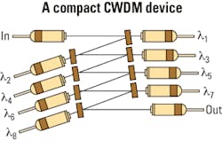
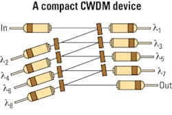
To meet these additional requirements in CWDM passives, the free-space optical bench design is the best choice for the integration platform. In a compact free-space CWDM device (Figure 1), the light carrying multiple-wavelength signals enters an input fiber. At the first channel port, one wavelength is separated by a dielectric thin-film filter. The in-band spectral signal passes through the filter before being coupled into a receiving collimator, while the remaining signals are reflected to the next channel port, continuing until all specified channel signals have been dropped. This way, the interchannel coupling is done through free-space by a zig-zag of the collimated beam instead of by fiber splicing and routing.
A closer look at such free-space optical benches reveals that they can help systems designers meet the CWDM objectives outlined better than conventional three-port alternatives.
The free-space optical bench provides superior performance, particularly in the areas of low loss and flexibility.
Ultralow loss. There is no cost-effective optical amplification technology available to cover all S-, C-, and L-bands used in the typical CWDM channels. The maximum distance a signal can reach is determined predominantly by the power attenuation of the passive devices the signal traverses. For a standard G.652 fiber, the attenuation level is about 0.2 dB/km. In other words, decreasing loss by 1 dB increases signal reach distance by 5 km, and a 2-dB decrease in loss can gain an additional 10 km of transmission distance.
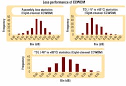
Based on a previous analysis, compact CWDM devices based on free-space cascading intrinsically have much less insertion loss than conventional three-port modules. Figure 2a depicts the assembly loss statistics of an eight-channel compact CWDM (CCWDM) module. For a batch of 140 units, the average loss is 0.49 dB. In other words, on average, the maximum loss of an eight-channel device is only 0.49 dB when assembled. Compared with its counterpart, the three-port-based module, a CCWDM saves almost 2 dB in the loss budget.Loss variation with environmental change is another very important factor, especially for CWDM devices that may be used in an outdoor environment with ambient temperatures ranging from -40° to +85°C. Temperature-dependent loss (TDL) is mainly related to component fixation processes and package designs. In one proprietary design, the filters are mounted securely onto their integration substrate using appropriately processed sidewalls, minimizing the risk of minor component positional changes in both angular and translational directions. This design produces better TDL performance (Figures 2b and 2c). For an eight-channel device and for temperatures ranging from -5° to ~+65°C, the average TDL is 0.17 dB and for -40° to ~+85°C, it is only 0.22 dB.
Flexibility. In a free-space device, individual components are optically cascaded by the filters acting on the collimated input beam. This feature allows the insertion of other optical or optoelectronic components in the cascaded beam to broaden the scope of substrate-level integration and thus increase functionalities.
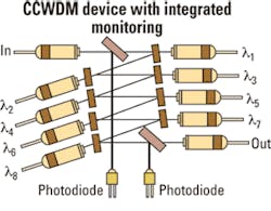
Figure 3 is an example where a tap monitoring function is integrated. The tap ratio of the filter on the monitoring channel determines the responsivity required by the detector, but typically 15 mA/W is sufficient. With tap monitoring at the input port, a user can monitor the incoming traffic signal level. On the other hand, with tap monitoring at the output port, a user can diagnose the signals out from this device node.
Compared with conventional three-port cascading modules, the dimensions of a free-space cascade device are significantly smaller, as the cumbersome fiber routing and extra collimator overhead are eliminated. To put the comparison into perspective, a conventional CCWDM package measures 40×28×6 mm, or approximately one-tenth the size of a standard three-port module.However, the fiber I/O ports are still on both sides of the package. Thus, a more desired version with packaging dimensions of 38×35×8.5 mm has been designed so that all fiber access ports are placed on one side of the device. Using the same fiber bend radius limit, routing with a one-sided device saves half of the routing space overhead, making it fit better with on-board integration design rules. It is possible that this type of device may one day even eliminate fiber routing altogether.
Once an optical network has been installed, the service life becomes a major concern. Telcordia GR-1209-Core and GR-1221-Core specify a method to simulate real-life conditions using various specially designed test procedures. These tests are generally applied only to component-level devices, like a three-port filter. The criterion for passing all these experiments is a less than 0.5-dB loss change.
However, the reality is that for a single three-port filter, it is not very difficult to meet the GR-1221-Core tests by showing a less than 0.5-dB loss change before and after a test. But a cascade of eight such three-port filters that individually passed GR-1221-Core tests may have a maximum insertion loss change up to 4 dB, a condition that is not acceptable to any system integrator.
For CCWDM modules, the multichannel integration is done at the device level and on a common substrate within the package. Proper process designs and rigorous controls enabled qualification results in which all seven testing categories are well within the GR-1221-Core-specified pass/fail criteria, which again were designed for individual devices, not modules. Subjecting a module-like device to individual channel qualification effectively tightens the qualification criteria by 8×. In fact, the largest insertion loss change observed among samples passing through all seven testing areas is 0.29 dB, demonstrating a superb reliability of this integration technology.
Substrate level integration through free-space cascade of thin-film filters shows many advantages over traditional three-port devices made into modules for CWDM applications. Not only do modules created with the cascading method have a much more compact dimension but they also have much lower insertion loss, lower material costs (especially when more functions are integrated), and better overall device reliability.Daoyi Wang is senior optical engineer and Yao Li is chief technologist at Alliance Fiber Optic Products Inc. (www.afop.com).


