CWDM solves wireless backhaul ‘router to tower’ issues
By DR. FRANCIS NEDVIDEK and DAVID ATMAN
The avalanche of mobile data traffic around the world is exposing vulnerability in the wireline-based backhaul infrastructure: a bottleneck in the first mile “tower to router” link.
Classic fiber exhaust explains much of this problem. There’s simply not enough capacity to accommodate the increasing number of gigabit and 10G links. Another factor is the desire – or even requirement – of many wireless carriers for dedicated links through their connectivity supplier’s network. They may even demand dedicated backhaul fiber strands to connect access and core meshes with mobile tower sites.
Let’s examine first-mile fiber challenges from several angles. We’ll survey the options and underscore the advantages of CWDM, look at the outside plant (OSP) connectivity involved in upgrading backhaul architectures, show how CWDM can expand fiber capacity while eliminating network elements, and look at CWDM’s ability to create virtual fibers and add even more capacity.
The value of CWDM
Before assessing the technology options, here are the requirements that operators must satisfy in their first-mile backhaul networks:
- Segregation of bandwidth on a per-wireless-carrier basis, according to service-level agreements (SLAs).
- Guaranteed bandwidth of up to 10 Gbps per first-mile backhaul link.
- Uncomplicated and reliable operation (truck-roll avoidance).
- Provisioning simplicity.
- Reach of up to 80 km “tower to the router” in the first mile but typically much less.
- OSP environmental hardening.
- Ability to preserve legacy 1550- or 1310-nm fixed connections.
The technology options for this portion of the network include active optical networking, passive DWDM, and passive CWDM.
Active optical. As an approach to address wireless backhaul congestion, active optical networking equipment typically amounts to overkill. The complexity of active methods presents an abundant superset of features and functionality that the operator pays for in hardware costs, software licensing, ongoing maintenance, electrical power, and upgrade costs. Segregating or partitioning bandwidth occurs at a logical level within the active electronics. But these higher-level logical approaches yield only best-effort bandwidth performance when emulating individual physical connections.
Then there are costs related to training personnel to maintain and manage proprietary network gear. Associated operating, spare-stocking, and repair costs further diminish return on investment (ROI). Active optical equipment is best placed in close proximity to the network core; unsophisticated and low-cost passive gear belongs in the access and middle-mile networks.
Passive DWDM. DWDM represents a more practical option. Where the number of connections or channels exceeds 16 and creates transmission capacity requirements of up to 160 Gbps (as in 10 Gbps × 16), DWDM technology may offer a viable alternative. But operators should be aware that DWDM is not the least expensive option and will not accommodate the plethora of form factors – from pedestal to line-card to central office (CO) rack – that characterize the first mile of the network. In that light, DWDM compares unfavorably with CWDM schemes.
Passive CWDM. An optimal balance between right-sized functionality and right-sized cost, CWDM satisfies the best-fit rule of Occam’s razor: Essentially, the simplest solution, all things being equal, is the best among more complex solutions. CWDM expands the capacity of existing fiber infrastructure by enabling individual fibers to function as multiple optical links; each link supports at least 10 Gbps over spans of up to 80 km. CWDM is unique in its ability to support legacy 1310- and 1550-nm single-fiber connections while permitting additional CWDM links via the same fiber pair.
Like DWDM, CWDM physically partitions connections at the physical layer into separate wavelengths that provide a unique and exclusive optical connection for each 10-Gbps traffic channel. The flexibility of CWDM facilitates cell-site capacity planning and design. Adding CWDM to an existing legacy fiber network is straightforward; both previously deployed and newly introduced channels are handled similarly, which means legacy channels are relayed and routed undisturbed. CWDM thus provides the simplest, most robust, and yet most multifaceted option for future expansion.
Backhaul upgrades
Several connectivity issues affect upgrades to a wireline network operator’s backhaul architecture.
In a typical radio-access-network OSP backhaul network, the feeder cable often extends several kilometers from the CO or aggregation point to a remote terminal (RT) in the vicinity of the wireless tower or cell site. In such situations, it is not uncommon to be confronted with an existing link comprising only a limited number of 6, 8, or 12 fiber strands, with electrical supply lines accommodating the optical cable along the same trench to the distribution terminal (DT). On the radio-network-controller (RNC) side, twisted-pair or coax carries mobile telephone and community microwave relay services from the tower. WiMax and other private dedicated or industrial and security antennas may be co-located at the tower as well.
FIGURE 1. Linear architecture with intermediate add/drop nodes
It is relatively easy to expand legacy installed fiber that supports low-bandwidth 2G and some 3G wireless services by upgrading the speeds of the CO and RT transceivers or adding blocks of four CWDM channels. Bandwidth-hungry 4G and LTE services in most cases, however, will require expansion of the optical bandwidth of the CO-to-RT link and very possibly converting the RT and DT links and the coax tower drops to fiber as well.
Whether installing twisted-pair, coax, electrical power grid cabling, or fiber, trenching and duct engineering represent the majority of costs. When the opportunity arises, laying flexible and future-proof optical cable (48-plus strands) yields a very high ROI and virtually eliminates future capacity restrictions. By the same token, the business case for upgrading the CO-to-RT link (middle mile) part of the OSP using CWDM wins handsomely over any option involving retrenching.
Capacity expansion
Boosting the capacity from the CO straight through to the DT via WDM can easily multiply the bandwidth of existing DT fibers – and eliminate the RT in the process. Two scenarios that enable new efficiencies involve connecting with wireless service providers (WSPs) and linking up a series of cell sites. Not all configurations, however, are amenable to these kinds of upgrades.
The first scheme increases fiber capacity from the CO to the DT, but also extends the CWDM channels all the way to the WSPs. There is ample fiber in today’s fiber cables to permit dedicated fibers running from the CWDM enclosure to the wavelength multiplexers that belong to each WSP. When several WSPs share facilities at each tower, individual gear may be compartmentalized into a so-called base station hotel, or fibers may run directly to towers outfitted with remote radio head technology.
Another architecture that takes advantage of CWDM consists of stitching together a series of cell sites along a fiber (four in this case) using the add/drop capabilities of CWDM. One such example is shown in Figure 1. Here a CO serves four cell sites with four pairs of wavelengths. A wavelength pair is added or dropped at each cell site. Since cell sites may reside tens of kilometers from the CO, minimizing insertion loss and selecting the appropriate optical power of transceivers become an essential priority. Individual cell sites may be housed in pedestals, small cabinets, and even suspended or buried in pods.
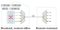
FIGURE 2. Using CWDM to multiply bandwidth for critical fiber-limited sections.
Depending on the particular regulatory situation or jurisdiction, not all WDM upgrade configurations may be practicable. Regulations may prohibit certain digital multiplexing of data or channels from particular subscribers. Others traditionally prefer dedicated fiber strands. Circumstances that require dedicated access fiber(s) may be accommodated in the middle mile through consigning WDM capacity or other fiber strands.
Furthermore, transmission reliability and incorruptibility concerns typically arise with respect to latency. Networks that transport SONET/SDH overhead or Frame Relay or pseudowire protocols strive to eliminate delays from provisioning, queuing, buffering, switching, or other electronic processing. WDM technologies offer one of the more effective approaches to minimizing latency because end-to-end delays are essentially reduced to the propagation speed of the optical signal through the optical link.
Virtual fibers, more capacity
An alternative architecture uses CWDM multiplexers to partition a single fiber strand (or pair) and in effect create virtual fibers. CWDM multiplexers are placed at the CO and in a remote enclosure, as depicted in Figure 2.
A CWDM system uses 1 to 16 wavelengths based on the ITU-T standard grid (and two more channels of the full ITU complement of 18 channels if low “water peak” fiber has been deployed). The transmission equipment at the cell site can use CWDM small-form-factor pluggable (SFP) transceivers. If not, separate CWDM transponders may convert low-power 1310-nm signals to the desired CWDM wavelength. CWDM SFPs and transponders reliably span fiber transmission distances of 60 km or more.
FIGURE 3. Upgrade of an existing access network to support additional wireless traffic.
A CWDM system can scale as capacity demand from the wireless subscribers grows. Operators can dedicate additional wavelengths to particular wireless sites in anticipation of “lighting up” addition channels. Flexible transmission rate per wavelength permits wireless providers to increase bandwidth to particular cell sites, independent of the WDM equipment. Alternatively, adding or dropping more wavelengths can increase link capacity.
Boosting capacity of the OSP infrastructure using CWDM technology adequately relieves wireless bandwidth bottlenecks in a vast majority of cases. But for situations where 18 CWDM channels do not suffice, overlaying DWDM wavelengths onto the CWDM grid permits further expansion of transmission capacity.
But the option to adopt DWDM connectivity carries the attendant need for controlled environment enclosures and deployment of the appropriate (more costly) DWDM transceivers. DWDM upgrades or deployments also require the right electrical power to support the additional equipment and thermal regulation. Supplementary space requirements may arise in RTs that serve as DWDM add/drop locations.
Finally, operators may need to add wireless capacity to existing access networks where the network subscription areas overlap with cell phone, same-service-provider WiMax, and even microwave and private wireless footprints. In such circumstances, operational continuity and integrity of the legacy subscription base must be maintained while augmenting bandwidth to individual wireless sites.
Figure 3 demonstrates such a situation. The network segment typically composes part of a ring in urban areas, but the topology often branches to a linear configuration in rural or remotely populated areas. Both configurations are possible where new wireless capacity supplements the existing 10-Gbps connectivity that links subdivisions, enterprises, and institutions to the co-location sites, distribution hub, and headend.
Today and tomorrow
The rising tide of wireless backhaul traffic is creating bottlenecks in the wireline networks that serve them. CWDM relieves backhaul bandwidth exhaustion in harmony with the dictum that the simplest choice, all things being equal, tends to be the best.
Applicable in a range of scenarios, CWDM demonstrates admirable flexibility – especially when combined with highly reliable, customizable, and compact low-cost components. The technology solves the problem of future expansion with a minimalist approach: only as much as you need, when you need it, without expensive or unnecessary extras. CWDM is thus able to remedy the “tower to the router” backhaul link challenges of today and tomorrow.
DR. FRANCIS NEDVIDEK is CEO of Cube Optics AG and DAVID ATMAN is president of Lindsay Broadband Inc.


