PMD field audit reveals investment losses
Polarization-mode dispersion (PMD) is a parameter of great importance in modern optical communications. PMD-induced temporal broadening has the same impact on system performance as that created by chromatic dispersion (CD), although it is caused by a different mechanism. The excess PMD causes intersymbol interference, resulting in increased bit-error rates in digital systems. Thus, just as does CD, PMD limits the information transmission capacity per optical channel in long-distance optical telecommunications systems.
An important difference between the two types of dispersion is that CD can be compensated for via reasonably simple means, while PMD compensation is much more complex and costly and may not be a viable investment in many cases. Therefore, it is important for service providers to learn as much as they can about the PMD characteristics of the fiber in their networks. FiberWork, a company that specializes in PMD diagnostics, has conducted a measurement audit of PMD in fibers installed between 1997 and 2002 in Brazil. While this audit has clear implications for carriers operating in that country, the fact that a reasonable amount of the fiber was manufactured elsewhere in the world and imported into Brazil means the audit results should also be of interest to carriers worldwide that installed new fiber during the same time period.
The audit was conducted using a proprietary method of PMD diagnostics. The network diagnostics comprise detailed field data acquisition and in-depth analysis. The outcome is a set of recommendations intended to aid in network design optimization, capital and operating expenditure savings, better exploitation of fiber transmission capacities, and futureproofing of the network. The diagnostics also can indicate alternatives for PMD compensation or for postponing such compensation.
A commercial PMD test setup based on the interferometric method was used for the PMD field measurements on which the audit was based. In this method, a broadband polarized light source and a PMD analyzer are placed on opposite ends of the fiber link. Due to the uncertainty introduced by wavelength averaging and the random nature of PMD, the audit technicians collected several PMD measurement readings for the same fiber during long periods of time. The collected field data was then statistically analyzed to get the PMD results.
The PMD measurement audit under discussion is similar to that compiled by Telcordia Technologies for the U.S. fiber plant for fibers installed between 1985 and 1996.* The current audit focused on a universe of 2,140 fibers installed between 1997 and 2002 in Brazil. Fiber route lengths ranged from 60 to 140 km. These fibers belonged to real world cables in working fiber plants. Different types of plants in different regions and climates of the country from well-known fiber and cable manufacturers were examined. In a second part of this study, the auditors grouped the data universe by plant type, forming sub-universes of buried, aerial, and optical groundwire (OPGW) PMD data. This process was then repeated and the data regrouped by sub-universes of cable manufacturer, cable age, and fiber type (standard and nonzero dispersion).
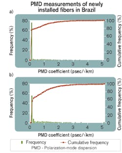
Figure 1a shows the summary of all PMD test results belonging to the considered database universe (i.e., 2,140 fibers installed during 1997-2002 in Brazil). It shows the relative frequency and cumulative frequency distributions of the installed-link PMD coefficients in psec/√km. (For more information on the difference between link PMD and the PMD of individual fibers, see the accompanying sidebar, “Link PMD provides the real picture,” p. 32.) It does not distinguish among plant type, cable manufacturer, installation age, or fiber type.
Figure 1a reveals that 19% of the fibers presented PMD coefficients ≥0.5 psec/√km and therefore did not comply with the requirements of current transmission technologies such as 10-Gbit/sec systems. PMD requirements for future transmission technologies such as 40-Gbit/sec systems are much tighter. Thus, the percentage of fibers that will not comply with this technology was even greater.Different installed cables usually comprised different numbers of fibers. Additionally, quite often not all fibers in a cable were measured. On the other hand, usually a pattern found for a sample of fibers within the same route cable provided a reasonable representation of the whole set. Thus, to avoid biasing the audit toward some fiber routes with greater amounts of measured fibers in detriment to other routes with fewer measured fibers, the auditors conducted a per-route balanced analysis. That was done by first calculating the PMD frequencies (in percent) per network span, then working out the arithmetic mean of all spans. The result is shown in Figure 1b and reveals worse results than those shown in Figure 1a: 30% of the route fibers presented PMD coefficients ≥0.5 psec/√km.
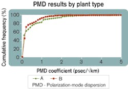
Figure 2 presents the analysis of data sub-universes grouped by plant type. Buried and OPGW data are presented. The aerial data of the database came from fibers installed before the period considered and thus are not shown. Specific plant types are not revealed. Only cumulative frequencies are shown to facilitate comparison.The sub-universes displayed in Figure 2 were weighted. That was done to avoid biasing the results toward specific manufacturers or fiber types. Weighting was done that equalized the amount of data per manufacturer and fiber type (i.e., first calculating the PMD frequencies in percent per cable manufacturer in each specific plant type, then working out the arithmetic mean for all manufacturers in that plant type). Figure 2 reveals that about 24% of “A” type plants experienced PMD coefficients ≥0.5 psec/√km as compared to 20% of the “B” type fiber plants. So it shows that some plant types may be a little more susceptible to higher PMD levels than other plant types.
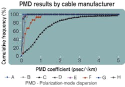
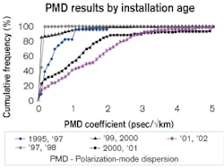
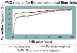
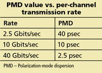
Figure 3 presents the analysis with respect to cable manufacturer. Specific manufacturer names are not revealed. This graphic reveals one manufacturer with 77% of its installed cabled fibers presenting PMD coefficients ≥0.5 psec/√km. A second manufacturer has 20% of its fibers presenting PMD coefficients ≥0.5 psec/√km. The other manufacturers have 0% of their installed cabled fibers experiencing PMD ≥0.5 psec/√km. This graphic also reveals that 0.2- to 0.3-psec/√km figures are feasible for most of the manufacturers surveyed. So fiber-network operators can specify these or even better values in their new RFPs as the 99.99%-acceptable “link PMD coefficient.”This graph yields a slightly better result than Figure 1a for 10-Gbit/sec systems. That’s because most of the surveyed concatenated spans were shorter than 400 km. A per-route balanced analysis of these concatenated data also was conducted as well (see Figure 5). It shows that 5%, 29%, and 39% of such concatenated links exhibited PMD values equal to or greater than 40, 10, and 2.5 psec, respectively, which is a worrisome result. It should be noted that most owners of PMD-impaired fiber networks have not yet recognized their investment losses, because they are still operating their DWDM networks at low channel rates and/or at low DWDM channel counts.
The audit reveals that 19% of the surveyed installed cabled fibers presented PMD coefficients ≥0.5 psec/√km and therefore did not comply with the requirements of current transmission technologies such as 10-Gbit/sec systems. By conducting a per-route balanced analysis of the same data, the outcome got worse, with 30% of the route fibers presenting PMD coefficients ≥0.5 psec/√km. This audit also reveals that 18% (or 39% when a per-route balanced analysis is considered) of the actual concatenated spans will not comply with 40-Gbit/sec technology (without taking into account the PMD of additional network elements).
It was found that the frequency of high-PMD fibers varies among the surveyed plant types by only 4%. Cable manufacturers displayed extremes of 0% and 77% of their installed cabled fibers presenting high PMD coefficients. It was observed that PMD remains a very worrisome problem even in the most recent fiber installations. It also was revealed that 0.2-0.3 psec/√km are feasible figures for most cable manufacturers, and so fiber network operators can specify these or even better values in their new RFPs as the 99.99%-acceptable “link PMD coefficient.”
The PMD audit is a sample of the PMD status of newly installed fiber plants in Brazil. Butit must be pointed out that the relative sizes of the surveyed data sub-universes may not correspond to their respective market shares. To create a realistic picture of the full Brazilian fiber plant, these sub-universes should be weighted by their market shares. Also, this survey takes into account only fibers installed in Brazil. But a reasonable amount of such fibers and cables were manufactured elsewhere in the world and imported into Brazil. Therefore, the PMD audit also may be taken as a reasonable sample of the PMD status of installed fiber plants around the world during the fiber-installation boom era.
High PMD means that fiber-network owners will find it difficult to exploit high transmission rates per DWDM channel, thus limiting the future of their fiber networks. Moreover, as PMD induces higher bit-error rates, optical signal-to-noise-ratio margins become lower, and therefore fewer DWDM channels can be lit in high-PMD fibers. Certainly, carriers should avoid spending millions of dollars on the latest high-speed, high-channel-count DWDM system if their installed network PMD can accommodate only a half-dozen 2.5-Gbit/sec channels.
Forward error correction can alleviate the PMD problem but only to a certain extent. PMD compensators also can be used but at the cost of bringing complexity and higher investment in the network. Fiber networks are expected to have a profitable lifetime of 25 years. However, if a newly installed fiber bears PMD levels higher than those required by current commercial transmission technologies, then such an investment has not been wise.*J. Peters, A. Dori, and F. Kapron, “Bellcore´s Fiber Measurement Audit of Existing Cable Plant for Use with High Bandwidth Systems,” NFOEC´97 proceedings, September 1997.
Sergio Barcelosis chief technology officer at FiberWork Optical Communications (Santa Clara, CA, and Campinas, Brazil). He can be reached at [email protected].
Because of its statistical nature, the polarization-mode dispersion (PMD) of an optical link, “link PMD,” is the root mean square value of the concatenated fibers’ PMD. Thus, it is more useful to make recommendations based on this fact, rather than specifying an individual fiber’s PMD. That has been an important issue at the standardization bodies, which have recently released technical recommendations taking that into account. Newer usage recommends specifying a maximum link PMD coefficient (PMDQ) and a probability (Q) of exceeding this maximum†:
Probability of (XM > PMDQ) = Q,
where XM is the actual link PMD coefficient calculated supposing a number of M concatenated fibers.†R.J. Whitman, “Polarization Mode Dispersion (PMD): What is the statistical method for determining link PMD and why is it important,” whitepaper, www.corningfiber.com/library/paper WP3229, Corning Inc., March 1999.
††H. Kogelnik, L.E. Nelson, and R.M. Jopson, “Polarization Mode Dispersion Impairments in Lightwave Transmission Systems,” OFC 2002 proceedings, March 2002 and references therein.
†††W.B. Gardner, “PMD is challenged by 40 Gbits/sec,” Lightwave, April 2004, p. 14.
