Application of DWDM architectures in cable-TV networks
The popularity of the Internet and other two-way services like near-video-on-demand and Internet protocol (IP) telephony have created a significant need for bandwidth in local access networks. Cable operators are well positioned to offer these services since they already own a high-bandwidth "pipe"--the coaxial cable--with access to a majority of U.S. households. The challenge is to transport these two-way services cost-effectively over a cable-TV network that has traditionally only provided broadcast video.
Cable operators are increasingly looking at dense wavelength-division multiplexing (DWDM) as the answer to this problem. The ability of DWDM to deliver these services over existing hybrid fiber/coaxial-cable (HFC) network infrastructure is appealing to cable operators who want to offer new revenue-generating services without major upgrades to their HFC plant.
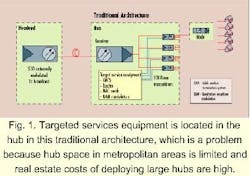
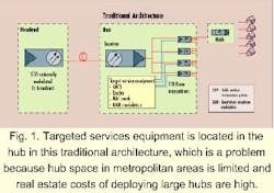
The traditional point-to-multipoint cable-TV architecture consists of a headend with a 1550-nm broadcast video transmitter that typically transmits 80 analog video channels to the hub (see Fig. 1). The targeted digital information is transported to the hub over a dedicated Synchronous Optical Network (SONET) ring. At the hub, the video channels are combined with targeted digital information, and transported to the node using 1310-nm transmitters. From the node, the combined video and digital channels are delivered to the subscriber's home over coaxial cable.Typically, a hub feeds about 32 nodes and each node serves about 1000 homes. Since the bandwidth available to a subscriber drops as the number of subscribers served by each node increases, cable operators are planning to deploy more nodes deeper into residential areas and reduce the number of subscribers served by each node. Already, there are plans to limit the number of homes per node to 500 within a year and to 50 within two to three years, which will substantially increase the quantity of equipment needed to provide targeted services.
Notice that in the traditional architecture, targeted services equipment such as routers, and cable modem termination system (CMTS) and quadrature amplitude modulation (QAM) devices are located in the hub. This arrangement is a problem in dense metropolitan areas where hub space is limited and the real estate cost of installing large hubs is significant. The installation of dedicated SONET rings from the headend to the hub adds cost as well.
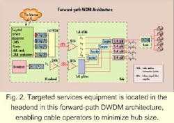
DWDM enables the cable operator to locate most of the sophisticated targeted service equipment in the headend and increase overall network bandwidth without major HFC plant upgrades. By using this innovative architecture, the operator can achieve a reduced hub size, lower technical-support costs, and improved reliability, all of which can result in more cost-effective provision of targeted services.In the downstream architecture shown in Figure 2, the targeted services equipment is located in the headend, which is much larger and has more room for expansion. At the headend, a transmitter operating at 1545 nm provides broadcast of 80 analog video channels. Internet, telephony, and other targeted service data is converted from the baseband digital format to an RF signal using a QAM device and RF up-converters.
QAM is a method of converting a baseband digital bit stream to an intermediate frequency (IF) signal that can be up-converted into an RF signal for transport over HFC networks. QAM devices are available in different formats. For example, a 64-QAM occupies a 6-MHz band and is capable of modulating 27 Mbits/sec of data, while a 6-MHz 256-QAM has a bit rate of 38 Mbits/sec. As the bit rate of the QAM increases, so too does the signal-to-noise ratio (SNR) needed to maintain a certain bit error rate. Therefore, it is necessary to pick a QAM format that balances the data rate against the SNR limitations of the system.
Several of these QAM channels are combined using an RF coupler and drive a directly modulated transmitter operating on the International Telecommunications Union (ITU) grid. The output of several ITU transmitters, spaced 1.6 nm apart, is combined using a wavelength-division multiplexer and transported to the hub. At the hub, the wavelengths are demultiplexed, combined with the broadcast analog video channels, and transported to the node for distribution to the subscriber's home over coaxial cable.
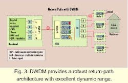
In a typical DWDM system, the analog video channels occupy the RF spectrum from 50 to 550 MHz, while the QAM channels are placed in a 50-MHz slot from 550 to 600 MHz. The optical power level of the QAM channels is adjusted to be 10 dB below the analog signal to minimize distortion effects in the analog band. As stated previously, each 64-QAM occupies a 6-MHz band and can carry 27 Mbits/sec of bandwidth. Up to 9 QAMs can be transmitted with a single ITU laser before the distortion effects caused by the QAMs degrade the performance of the broadcast analog video channels. So the total downstream bandwidth in an 8-wavelength system can be as high as 1.9 Gbits/sec. Assume that a hub serves 32,000 homes, that there is 20% penetration of cable modems, and that 25% of the subscribers are online at any one time. This assumption projects a profile of 1600 subscribers online at peak operating times who can access the Internet at 1.2 Mbits/sec.The return path from the home to the headend is an important part of this architecture (see Fig. 3). It is necessary to combine return signals from several nodes at the hub and transmit the combined return back to the headend with minimal fiber counts. The return signals in the 5- to 42-MHz band are transmitted from the node to the hub using a 1310-nm return-path transmitter. At the hub, the signals are received and converted back into RF. The RF signals from several nodes are then combined and drive a return-path transmitter operating on the ITU grid. The output of several ITU transmitters is multiplexed and transported to the headend where the wavelengths are demultiplexed, converted into RF, and fed to the CMTS. The CMTS controls the timing at which the nodes transmit back data to prevent data collisions.
Another problem in the return path is noise accumulation. Since the return signals from various paths are combined, the noise on these paths accumulates, fluctuating the RF level of the combined signals. The dynamic range of the return path is a measure of how much fluctuation the return-path system can tolerate and still maintain a certain acceptable bit error rate at the headend. Out of all the return-path technologies available, DWDM offers the highest dynamic range and provides a robust return-path architecture.
DWDM significantly reduces the rack space requirement in the hub. The router, QAM devices, and MAC cards are transferred to the headend. The hub contains only optical amplifiers, passive optical components, return-path receivers, and transmitters which can now easily fit into a cabinet rather than requiring a dedicated building. The reduced quantity and lower complexity of the equipment also increases the reliability of the hub and results in reduced service costs.
Scalability is another advantage of using DWDM. Initial deployment could consist of a single ITU transmitter feeding eight or more nodes. As the demand for targeted services increases, the operator can add capacity by adding ITU transmitters at different wavelengths and reducing the number of nodes fed by each transmitter. This scenario requires minimal initial equipment investment and properly defers expansion until required at some future time, when equipment costs will be even lower. This increase in capacity by wavelength addition requires minimal additional equipment at the hub--typically only changing passive optical splitters and optical multiplexers and demultiplexers, with an increase in optical-amplifier power.
In terms of equipment cost, the main components of the system, such as the ITU lasers, multiplexers, and demultiplexers, are the same as those used in the telecommunications industry. We can expect costs for these components to drop quickly in the next few years as unit volumes continue to rise.
As an evolving cable industry begins its own sophisticated service offerings, it is looking closely at upgrade paths that meet higher bandwidth demands cost-effectively. DWDM is fast proving a scalable, robust architecture that makes possible the delivery of broadcast analog video and targeted digital services over a conventional HFC network. It has the advantage of decreasing hub size and support requirements while increasing reliability and a scalability that enables future expansion with minimum modifications to the HFC plant.
Ketan Gadkari is product marketing engineer, transmitter systems, at Harmonic Inc.


